

GHIELMETTI AG – 7UW50 - Technische Dokumentation
ROR/09.02.2021
Page 12 of 19
13.3
Test and commissioning
13.3.1
General
Prerequisite for commissioning is the completion the preparation procedures in capture Fehler!
Verweisquelle konnte nicht gefunden werden..
Warning : Hazardous voltages are present in this electrical equipment during operation. Non-
observance of the safety rules can result in severe personal injury or property damage.
Only qualified personnel shall work on and around this qquipment after becoming thoroughly
familiar with all warnings and safety notices of this manual as well as with the applicable safety
regulations. Particular attention must be drawn to the following:
The earthing screw of the device must be connected solidly to the protective earth con-
ductor before any other connection is made.
Hazardous voltages may be present on all circuits and components connected to the
supply voltage or to the control signals
Hazardous voltages may be present in the device even after disconnection of the supply
voltage (storage capacitors!)
The limit values given in the Specifications (section 15) must not be exceeded at all, not
even during testing an commissioning
13.3.2
Tripping test
Warning : Primary tests shall be performed only by qualified personnel wich is trained in
commissioning of protection systems and familiar with the operation of thw protected object as well
as the rules and regulations (switching, earthing, etc.)
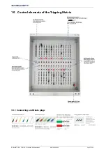
In order to test the tripping circuits, a control command must be given from a protection or
supervision relay which energizes the related matrix input (column). The corresponding switching
elements (master relays, circuit breaker coils) will be energized by the outputs (rows) of the matrix
device, in accordance with the settings of the diode plugs of the cross-bar distributor. The LEDs
assigned to the columns and rows under test must be illuminated and remain illuminated (latched).
In addition, the common trip indication must appear. All stored indication disappear after pushing
the “RESER” button on the front of the device.
Warning : After output of the trip command the switching device will be operated. Ensure before
each test, that switch-ing is permissible under the actual switchgear condi-tion. E.g. isolate circuit
breakers by opening the disconnectors at both sides.
Caution : The terminal limit of 1 A of the control inputs must be observed. When more than one
control input is subjected to the max. permissible continuous current, overload and damage can
result. Therefore, these test must be short-term tests. Observe a cooling-down period after each
test.
13.4
Making ready for service
Marshalling of the trip commands should be checked again, in case they were altered during the
tests.
Stored indications on the front plate should be reset by pressing the push-button "RESET LED" on
the front so that from then on only real faults are indicat-ed.
Summary of Contents for 674.114.913.02
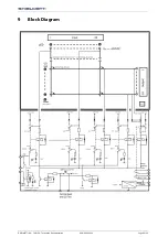
Page 6: ...GHIELMETTI AG 7UW50 Technische Dokumentation ROR 09 02 2021 Page 6 of 19 9 Block Diagram...
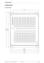
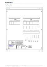
Page 15: ...GHIELMETTI AG 7UW50 Technische Dokumentation ROR 09 02 2021 Page 15 of 19 14 2 Back view...
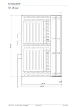
Page 16: ...GHIELMETTI AG 7UW50 Technische Dokumentation ROR 09 02 2021 Page 16 of 19 14 3 Side view...


