GHIELMETTI AG – 7UW50 - Technische Dokumentation
ROR/09.02.2021
Page 17 of 19
15
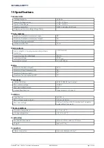
Specifications
Technical data
Voltage supply U
H
+250 V
DC
Range of voltage supply:
+120 … 370 V
DC
Input Voltage Range:
+180 … 250 V
DC
Power consumption:
0.5 W in standby, 45 W max.
Bridging period on auxiliary voltage failure:
≥50 ms to U
H
≥
250 V
DC
Display memory
Number of indication memories / Input:
28
Number of indication memories / Output:
10
Number of group memories:
1
Indication delay time:
≥5 ms
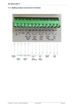
Alarm contacts
Alarm relays for «tripping command dispatched»
indication:
2 NO contacts
Switching capacity make/break:
20 VA
Switching voltage:
250 V
AC/DC
Permission current:
0,1 A @ 250 V
DC
Matrix
Number of columns (inputs):
2x14
Number of input indication LED:
28
Number of rows (outputs):
10
Number of output indication LED:
10
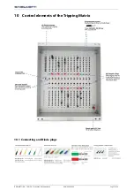
Diode plugs
GDS 621 ZS/20 sw:
674.212.002.00 (part number)
Max. reverse voltage :
1000 V
Max. permissible current:
1 A
Current flow direction:
from column (+) to row (-)
Insulation
Specification:
IEC 255-5
Max. voltage (input, output):
2,8 kV
eff
@ 50 Hz
Max. over voltage:
5 kV
peak
1,2/50 μs, 0,5 J, 3 positive and 3 negative
pulse within 5 sec. each
Climate conditions
Operation temperature:
-5 °C to +55 °C
Storage temperature:
-25 °C to +55 °C
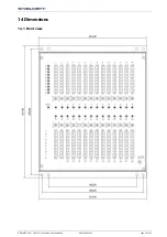
Construction
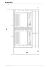
Mechanical dimensions:
W/H/D = 219.4 x 267.4 x 177.3mm
Weight:
approx. 4.7 kg
Connectors
Clamp-connectors:
max. wire diameter 2.5 mm²
Summary of Contents for 674.114.913.02
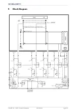
Page 6: ...GHIELMETTI AG 7UW50 Technische Dokumentation ROR 09 02 2021 Page 6 of 19 9 Block Diagram...
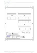
Page 15: ...GHIELMETTI AG 7UW50 Technische Dokumentation ROR 09 02 2021 Page 15 of 19 14 2 Back view...
Page 16: ...GHIELMETTI AG 7UW50 Technische Dokumentation ROR 09 02 2021 Page 16 of 19 14 3 Side view...


