
GHIELMETTI AG – 7UW50 - Technische Dokumentation
ROR/09.02.2021
Page 4 of 19
4.2
Safety Earth Ground
This is a Safety Class 1 product (a protective earth terminal GND is provided). An uninterrupted
safety earth ground must be provided from the main power source to the product input wiring
terminals, power, cord, or supplied power cord set. Whenever it is likely that the protection has
been impaired, the product must be made inoperative and secured against any unintended
operation.
5
Installation
5.1
Initial Inspection
Check the contents of the shipment for completeness and possible transport damage. If the
contents are incomplete or damaged, contact GHIELMETTI immediately to get the concerned parts
repaired or replaced.
5.2
Before Applying Power
Verify that the product is configured to match the available main power source per the input power
configuration instructions provided in this manual.
5.3
Servicing
Servicing, adjustments, maintenance or repair of this product may be performed by qualified
personnel only.
6
Disclaimer
This instruction manual does not purport to cover all details in equipment, nor to provide for every
possible contingency to be met in connection with installation, operation or maintenance. Should
further information be desired or should particular problems arise which are not covered sufficiently
for the purchaser's purpose, the matter should be referred to the local GHIELMETTI sales office.
The contents of this instruction manual shall not be-come part nor modify any prior or existing
agree-ment, commitment or relationship. The sales contract contains the entire obligations of
GHIELMETTI. The warranty contained in the contract between the parties is the sole warranty of
GHIELMETTI. Any statements contained herein do not create new warranties nor modify the existing
warranty.
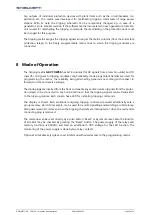
7
Functional description
The tripping matrix GKV 7UW50 is a component of a generator protection system. The tripping
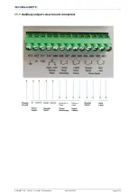
matrix provides a transparent, easily programmable facility for combining output commands of the
Summary of Contents for 674.114.913.02
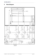
Page 6: ...GHIELMETTI AG 7UW50 Technische Dokumentation ROR 09 02 2021 Page 6 of 19 9 Block Diagram...
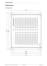
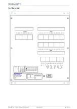
Page 15: ...GHIELMETTI AG 7UW50 Technische Dokumentation ROR 09 02 2021 Page 15 of 19 14 2 Back view...
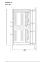
Page 16: ...GHIELMETTI AG 7UW50 Technische Dokumentation ROR 09 02 2021 Page 16 of 19 14 3 Side view...