

GHIELMETTI AG – 7UW50 - Technische Dokumentation
ROR/09.02.2021
Page 5 of 19
trip outputs of individual protection devices with plant items such as the circuit-breakers, de-
excitation etc. The matrix was developed for marshalling tripping commands of large power
stations. With its help, the tripping schematic can be temporarily changed, e.g. in case of a
generator circuit- breaker revision. If the software matrix incorporated in each generator protection
unit is used for marshalling the tripping commands, the marshalling in the protection units must
be changed for this purpose.
The tripping matrix assigns the tripping signals arriving at the matrix columns (from the solid-state
protection relays) to the freely programmable matrix lines to which the tripping modules are
connected
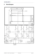
8
Mode of Operation
The tripping matrix GKV 7UW50 has 2x14 columns (for 28 signals from protection units) and 10
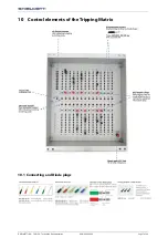
rows (for 10 signals to tripping modules). High reliability diode plugs (black handle) are used for
programming the matrix, the reliability being attained by generous over-rating with respect to
forward current and reverse voltage.
The diode plugs are inserted from the front and enable any vertical column (signals from the protec-
tion relays) to be connected to any horizontal line so that the tripping signals can be transmitted
to the tripping module. Each column has a LED for indicating tripping commands.
The display is stored. Each additional outgoing tripping command received additionally sets a
group memory, which, for example, can be used for remote signalling and switching a cubicle lamp.
All signals remain stored even when the tripping channels are interrupted or when the red central
connecting plug is removed.
The memories can be reset directly by a push-button "Reset" or by remote reset. Also the function
of all LED’s may be checked by pressing the "Reset" button. The power supply of the relays and
memory functions is 250VDC and feed an additional 5 VDC voltage for the LED function. The
monitoring of the power supply is done by two relay contacts.
Optional: A lockable acryl-glass-cover inhibits unauthorised access to the programming matrix.
Summary of Contents for 674.114.913.02
Page 6: ...GHIELMETTI AG 7UW50 Technische Dokumentation ROR 09 02 2021 Page 6 of 19 9 Block Diagram...
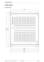
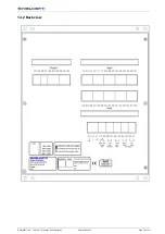
Page 15: ...GHIELMETTI AG 7UW50 Technische Dokumentation ROR 09 02 2021 Page 15 of 19 14 2 Back view...
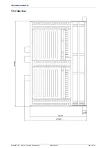
Page 16: ...GHIELMETTI AG 7UW50 Technische Dokumentation ROR 09 02 2021 Page 16 of 19 14 3 Side view...


