GHM Messtechnik GmbH – Martens
Kiebitzhörn 18 ● 22885 Barsbüttel ● Germany
Phone +49-40-670 73-0 ● Fax -288
www.ghm-messtechnik.de ● info@martens-elektronik.de
10
4.
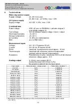
Controls and functional description
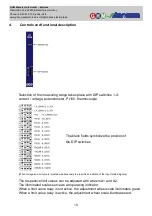
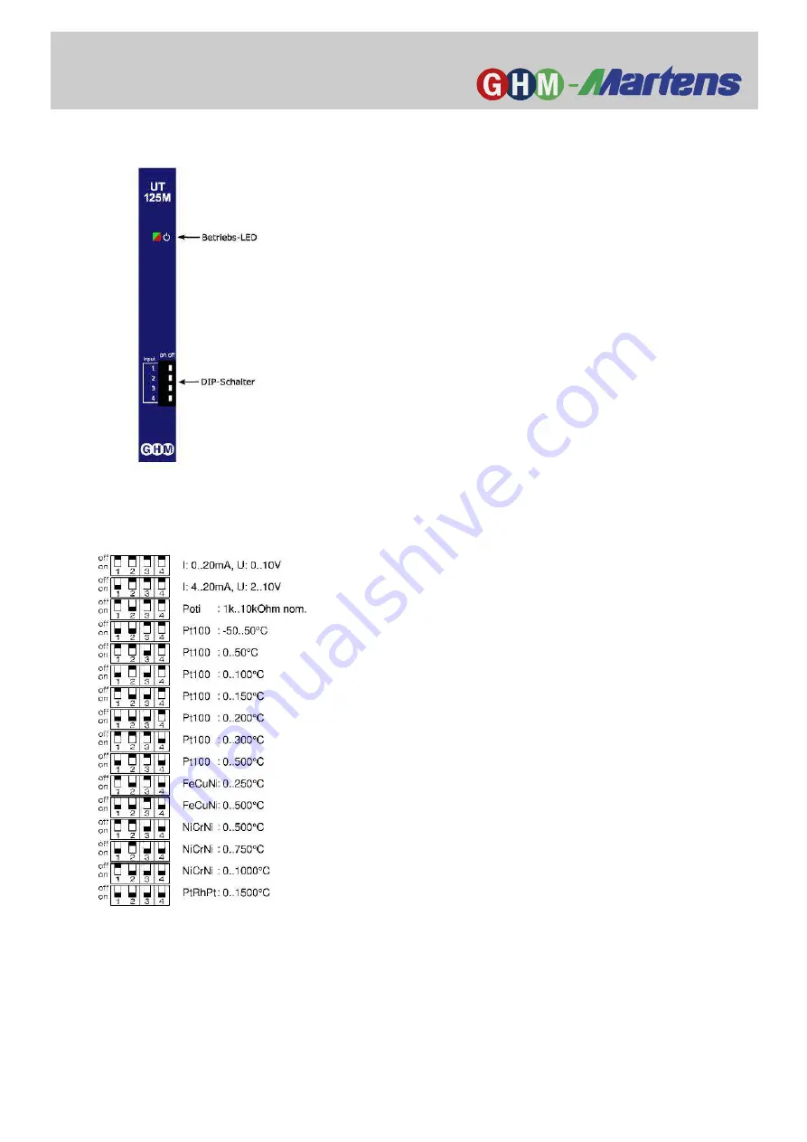
Selection of the measuring range takes place with DIP switches 1-4:
current / voltage, potentiometer, Pt100, thermocouple
The black fields symbolize the position of
the DIP switches
(When voltage and current are injected simultaneously the result is an addition of the input related signals)
The respective limit values can be adjusted with wheels A1 and A2.
The illuminated scales serve as an operating indicator.
When a limit value relay is not active, the adjustment wheel scale illuminates green.
When a limit value relay is active, the adjustment wheel scale illuminates red.


