background image


GHM Messtechnik GmbH – Standort Martens


Kiebitzhörn 18 ● 22885 Barsbüttel ● Germany  
Phone +49-40-670 73-0 ● Fax -288 
www.ghm-messtechnik.de ● info@martens-elektronik.de


10 

4.  Functional description 
 

4.1 

Controls 


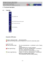
Operation LED states


     Green continuous light:   Normal operation. 
     Red slow blinking (one-second frequency): Errors at the measuring inputs 


In service mode 
     Red continuous light:   

The  trim  potentiometer  is  positioned  at  the  factory 
setting. 
(red light differs from normal operation) 

     Red rapid blinking: 

Position  of  the  trim  potentiometer  is  positioned 
above the calibrated factory setting. 


Turn anti-clockwise to reach the factory setting. 

     Green rapid blinking: 

Position  of  the  trim  potentiometer  is  positioned 
below the calibrated factory setting. 


Turn clockwise to reach the factory setting. 

Summary of Contents for MU125

Page 1: ...Operating manual Temperature measuring transducer MU125 Save for later reference www ghm messtechnik de Company brands of GHM English ...

Page 2: ...le 6 2 3 Connection diagram 6 2 4 PowerRail 7 2 5 Type plate 8 3 Assembly and installation 9 3 1 Mechanical assembly 9 3 2 Electrical installation 9 4 Functional description 10 4 1 Controls 10 4 2 Service mode 12 4 21 Check of factory settings 12 4 22 Output characteristic curve specification 13 4 23 Current simulation 15 5 Commissioning maintenance and service 16 5 1 Commissioning 16 5 2 Maintena...

Page 3: ...ly or not as intended The device is not suitable for use in explosion prone areas General safety instructions use This operating manual must be kept in a location such that qualified personnel can refer to it at all times Any processes described in this operating manual may only be carried out by trained qualified personnel who are authorised by the owner and wearing protective clothing All rights...

Page 4: ...een checked to ensure conformity with the described device However deviations cannot be entirely ruled out Therefore we cannot assume any guarantee for complete conformity The specifications in this document are checked regularly and any necessary corrections are incorporated into subsequent versions This document is subject to technical changes In addition all claims are based on the valid Standa...

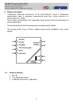
Page 5: ...re measurement value or resistance measurement value from various sensors to a current signal of 4 20mA The universal configurability of the measuring inputs reduces the stock requirement for various applications The measuring inputs and the analog output are galvanically isolated The housing width of only 12 5mm enables space saving installation in the switch cabinet 2 1 Scope of delivery MU125 T...

Page 6: ... ranges are linearised The device configuration is carried out with DIP switches The device can be supplied in a wide range between 20 125V DC or 20 253V AC A low cost version with 24V DC power supply is available Another version allows a 24V power supply via a mounting rail bus Power Rail 2 3 Connection diagram The input signal should be connected via separate two wire or three wire conductors Ea...

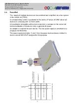
Page 7: ...responding version is available for the entire LP series of GHM carrier rail devices in a housing with 12 5 mm width A bus adapter compatible with series connection is clamped on the carrier rail before installation of the device to be supplied with power An adapter is required for each device The bus power supply is provided via a plug type terminal strip The power supply terminals 11 and 12 on t...

Page 8: ...Barsbüttel Germany Phone 49 40 670 73 0 Fax 288 www ghm messtechnik de info martens elektronik de 8 2 5 Type plate The type plate provides the most important identification data Type and article designation Technical data Serial number bar code Fig 3 Type plate ...

Page 9: ...on The device may only be installed by an electrician Compliance with the national and international regulations for installation of electrical and electronic systems applicable in the respective country of use is mandatory Voltage supply in accordance with DIN EN60664 1 SELV PELV Observe the connection diagram for installation of inputs and outputs The supply voltage connection is made at connect...

Page 10: ...ond frequency Errors at the measuring inputs In service mode Red continuous light The trim potentiometer is positioned at the factory setting red light differs from normal operation Red rapid blinking Position of the trim potentiometer is positioned above the calibrated factory setting Turn anti clockwise to reach the factory setting Green rapid blinking Position of the trim potentiometer is posit...

Page 11: ...symbolise the position of the DIP switch Sensor break and sensor short circuit Monitoring for sensor breaks and short circuits also takes place in the measuring ranges for Pt100 and Pt1000 sensors In this case the relays become inactive and the scale light blinks red The analog output drops to approx 0mA Trim potentiometer The 12 turn trim potentiometer can reduce the end value by 50 and change th...

Page 12: ... a constant value at the current output e g in order to test the reaction of connection devices The trim potentiometers can be used in both normal operation and service mode 4 2 Service mode A corresponding service mode can be selected for each of the two trim potentiometers via the DIP switches 4 21 Check of factory settings If the selected potentiometer is positioned at the calibrated factory se...

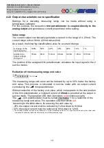
Page 13: ... simulates the input signal in the 2 service modes Reduction of the measuring range end value The measuring range end value can be reduced by up to 50 below the factory end value This process is simulated in service mode with an output current controlled by the trim potentiometer Without reduction of the factory end value which corresponds to the end position of the trim potentiometer a constant c...

Page 14: ...2mA 1 6mA 10 4mA 10 the output current must be increased by turning clockwise 1 6mA up to 13 6mA 12mA 1 6mA 13 6mA 40 the output current must be increased by turning clockwise 6 4mA up to 18 4mA 12mA 6 4mA 18 4mA The operation LED blinks green with a reduction and red with an increase Note The device can only detect a minimum measurement temperature of 50 C in most measuring ranges refer to Techni...

Page 15: ...reduction of the output current by 25 in service mode This value is multiplied by the greatest possible current change of 16mA 16mA 25 4mA Therefore an output current of 8mA must be adjusted in service mode for the trim potentiometer virtual zero point at 12mA minus 4mA reduction 8mA Accuracy A reduction of the end value or an increase of the start value always reduces the measuring accuracy The i...

Page 16: ... Commissioning 1 Ensure that the connections have been made as indicated in the connection diagram and the supply voltage is correct 2 Ensure that the terminals are firmly screwed in 3 After switching on the power supply check to ensure the operation 5 2 Maintenance Housing No cleaning or maintenance is required when operated as intended 5 3 Service Service of the device is only possible in the fa...

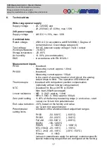
Page 17: ...130µA In the event of a sensor break or short circuit the analog output drops to 0mA The operation LED blinks red Thermocouple linearised with comparison position compensation optionally without internal compensation NTC linearised for B25 85 3977K or 3528K Max load 200µW averaged Linear resistance MR 0 2kΩ approx 1 4mA MRs 0 5kΩ 0 10kΩ approx 300µA Zero point setting 40 of the factory measuring r...

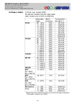
Page 18: ... 02 K 0 100 C 0 4 0 02 K 0 150 C 0 4 0 01 K 0 200 C 0 3 0 01 K 0 250 C 0 3 0 01 K 0 300 C 0 2 0 005 K 0 500 C 0 2 0 005 K Pt1000 50 50 C 0 4 0 01 K 30 70 C 0 4 0 01 K 20 40 C 0 4 0 01 K 0 50 C 0 6 0 02 K 0 100 C 0 4 0 02 K 0 150 C 0 4 0 01 K 0 200 C 0 3 0 01 K 0 250 C 0 3 0 005 K FeCuNi 0 250 C 1 0 0 04 K 0 500 C 0 5 0 03 K NiCrNi 50 250 C 0 7 0 05 K 0 500 C 0 5 0 04 K 0 750 C 0 4 0 03 K 0 1000 C ...

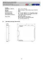
Page 19: ...8 mm Material PA6 6 light grey Flammability class V0 UL94 Weight 120 g Protection rating IP20 Screw terminals 0 2 2 5 mm AWG 24 14 removable coded Push in terminals 0 5 1 5 mm AWG 25 16 double connection spring type terminals 12A between the connections removable coded Power Rail 8A over the entire bus system power supply via removable terminals 0 2 2 5 mm AWG 24 14 6 1 Mechanical design dimension...

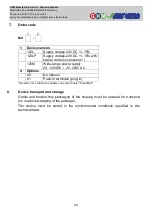
Page 20: ... DC 15 with carrier rail bus connection 125M Wide range power supply 20 125VDC 20 253V AC 4 Options 00 No options 01 Push in terminals plug in Delivery incl suitable bus adapter see also chapter PowerRail 8 Device transport and storage Gentle and tension free packaging of the housing must be ensured for transport no machine wrapping of the package The device must be stored in the environmental con...

Page 21: ... used and 3 a safety data sheet for the measuring medium is affixed to the outside of the package if the device has come into contact with a critical substance 10 Disposal Separation by material and recycling of device components and packaging must take place when the device is disposed of The valid legal regulations and directives applicable at the time must be observed The device may not be disp...

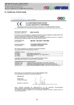
Page 22: ...GHM Messtechnik GmbH Standort Martens Kiebitzhörn 18 22885 Barsbüttel Germany Phone 49 40 670 73 0 Fax 288 www ghm messtechnik de info martens elektronik de 22 12 Certificate of Conformity ...

Page 23: ...GHM Messtechnik GmbH Standort Martens Kiebitzhörn 18 22885 Barsbüttel Germany Phone 49 40 670 73 0 Fax 288 www ghm messtechnik de info martens elektronik de 23 ...

Page 24: ...GHM Messtechnik GmbH Standort Martens Kiebitzhörn 18 22885 Barsbüttel Germany Phone 49 40 670 73 0 Fax 288 www ghm messtechnik de info martens elektronik de 24 V 01 00 03 ...

Reviews: