GHM Messtechnik GmbH – Martens
Kiebitzhörn 18
● 22885 Barsbüttel ● Germany
Phone +49-40-670 73-0
● Fax
-288
www.ghm-messtechnik.de
●
info@martens-elektronik.de
6
2.1.
Scope of delivery
TS125 or TS225
this operating manual
2.2.
Functional principle
The output relay and the diodes are controlled at the device front depending on
the status of the measuring inputs.
A maximum voltage of 8V is applied at a connected Namur sensor via the input
terminals. The sensor must limit the flowing current to two thresholds in
accordance with the Namur specification. Current lower than 1.2mA is identified
by the sensor as inactive; current higher than 2.1mA is identified by the sensor
as active. The range between 1.2mA and 2.1mA applies as hysteresis.
Alternatively, a switch contact can be connected. Then no current flows in the
open state and approx. 8mA flows in the closed state, wherein the previously
mentioned requirements are also fulfilled.
The front-side DIP switches can be used to select whether the input state is
directly or inversely transferred to the corresponding output relay.
The devices also offer the possibility of monitoring the input lines for a short-
circuit or wire break with the appropriate DIP switch settings.
In this connection, a current flow of less than 0.2mA applies as a wire break and
a current flow higher than 7mA applies as a short-circuit. With activation of this
monitoring function, the relays open in the event of a fault and the front-side
LEDs blink red. With connection of a simple switch contact, the error monitoring
must not be connected, because the error conditions are, in principle, always
fulfilled.
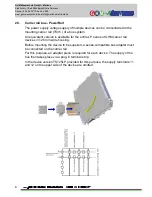
In order to also monitor the connecting lines for a mechanical switch contact,
resistors can be wired to the inputs according to the connection diagram below.
In the process, it is assured that the error thresholds recognised by the device
are only actually exceeded and/or undercut in the event of an error.


