background image


GHM Messtechnik GmbH – Martens


Kiebitzhörn 18 

● 22885 Barsbüttel ● Germany 


Phone +49-40-670 73-0 

● Fax 

-288 

www.ghm-messtechnik.de 

● 

info@martens-elektronik.de


8


2.5. 

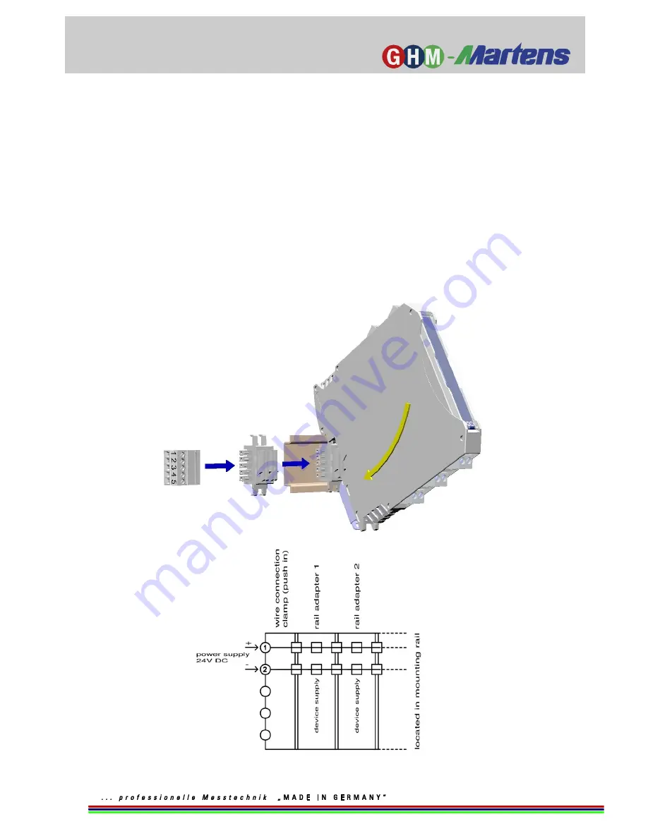
Carrier rail bus - PowerRail 

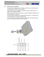
The power supply voltage supply of multiple devices can be concentrated in the 
mounting carrier rail (TS35 ) of a bus system. 

An equivalent version is available for the entire LP series of GHM carrier rail 
devices in 12.5mm wide housing. 

Before mounting the device to be supplied, a series-compatible bus adapter must 
be connected on the carrier rail. 

For this purpose, an adapter piece is required for each device. The supply of the 
bus then takes place via a plug-in terminal strip. 

In the device version TS125LP provided for this purpose, the supply terminals 11 
and 12 on the upper side of the device are omitted. 


Summary of Contents for TS125

Page 1: ...Operating manual Switch amplifier TS125 TS225 Save for later reference www ghm messtechnik de Companies brands of GHM English ...

Page 2: ...cope of delivery 6 2 2 Functional principle 6 2 3 Connection diagram 7 2 4 Type plate 7 2 5 Carrier rail bus PowerRail 8 3 Assembly and installation 9 3 1 Mechanical assembly 9 3 2 Electrical installation 9 4 Controls and functional description 10 4 1 TS125 1 TS125 2 TS225 1 TS225 2 10 5 Commissioning maintenance and service 14 5 1 Commissioning 14 5 2 Maintenance 14 5 3 Service 14 6 Technical dat...

Page 3: ...on of intrinsically safe sensors installed in Zones 0 or 1 and or 20 or 21 In the process the safety related characteristic data must be observed The approval for all intrinsically safe equipment is voided if it has not first been connected to an intrinsically safe circuit because compliance with the safety related characteristic data must be 100 guaranteed Therefore a safety test must be carried ...

Page 4: ...s Read the product description before commissioning the device Ensure that there are no limitations for use of the product for the relevant applications The owner is responsible for ensuring the fault free operation of the device The owner is obligated to ensure compliance and to observe the required work and safety measures of the current applicable regulations for the entire duration of use 1 3 ...

Page 5: ...series TS125 and TS255 are used in switch cabinets for the conversion and isolation of digital switching signals optionally also in explosive areas The devices are available in one or two channel versions All passive sensors such as switching contacts Namur initiators according to DIN EN 60947 5 6 or passive electronic outputs of third party devices can be connected to the optional intrinsically s...

Page 6: ...in the previously mentioned requirements are also fulfilled The front side DIP switches can be used to select whether the input state is directly or inversely transferred to the corresponding output relay The devices also offer the possibility of monitoring the input lines for a short circuit or wire break with the appropriate DIP switch settings In this connection a current flow of less than 0 2m...

Page 7: ...büttel Germany Phone 49 40 670 73 0 Fax 288 www ghm messtechnik de info martens elektronik de 7 2 3 Connection diagram 2 4 Type plate The type plate includes the most important identification data Type and article name Technical data Serial number bar code ...

Page 8: ...bus system An equivalent version is available for the entire LP series of GHM carrier rail devices in 12 5mm wide housing Before mounting the device to be supplied a series compatible bus adapter must be connected on the carrier rail For this purpose an adapter piece is required for each device The supply of the bus then takes place via a plug in terminal strip In the device version TS125LP provid...

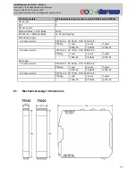
Page 9: ...ion rating IP54 3 2 Electrical installation The device may only be installed by an electrician The national and international regulations for connection of electrical systems in the respective user country apply Voltage supply in accordance with DIN EN 60664 1 SELV PELV The power supply is connected at Connections 11 and 12 of the plug in terminal strip Terminals 41 42 Channel 1 and 51 52 Channel ...

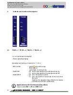
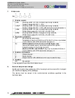
Page 10: ...rating elements per channel Ch 1 Ch 2 LEDs A1 A2 yellow with active relay blinks red wire break or short circuit Switch INV off active input switches the assigned relay on on active input switches the assigned relay off Switch ERR off error recognition inactive on error recognition of wire break or short circuit at the input Switches the assigned relay off with error status condition as delivered ...

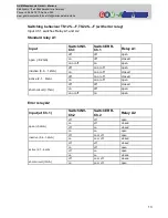
Page 11: ...o martens elektronik de 11 Ch 1 and Ch 2 switching behaviour Input Switch INV Switch ERR Relay open 0 2mA off off open on off closed on or off on open inactive 0 4 1 2mA off on or off open on on or off closed active 2 1 6mA off on or off closed on on or off open short circuit 7mA off off closed on off open on or off on open ...

Page 12: ...h INV Ch 1 off active input Ch 1 switches Relay A1 on on active input Ch 1 switches Relay A1 off Switch ERR Ch 1 off error recognition with Relay A1 inactive on error recognition of wire break or short circuit at input Ch 1 Switches Relay A1 off with error status Switch INV Ch 2 off active input Ch 1 or alternatively on error status switch Relay A2 on on active input Ch 1 or alternatively on error...

Page 13: ...open on off closed on or off on open inactive 0 4 1 2mA off on or off open on on or off closed active 2 1 6mA off on or off closed on on or off open short circuit 7mA off off closed on off open on or off on open Error relay A2 Input at Ch 1 Switch INV Ch 2 Switch ERR Ch 2 Relay A2 open 0 2mA off off open on off closed off on closed on on open inactive 0 4 1 2mA off on or off open on on or off clos...

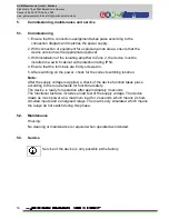
Page 14: ...on rating IP54 4 Ensure that the terminals are firmly screwed in 5 After switching on the power check for the correct switching function Note After the supply voltage is applied a check of the device function takes place according to the requirements for functional safety The device is ready for operation after approximately 3 seconds The functional test also includes a load test of the supply vol...

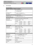
Page 15: ...n page 3 Wide range power supply Supply voltage 20 125VDC and 20 253VAC 47 63Hz max 1 5W ATEX limits for intrinsically safe inputs Uo 8 7V Io 19mA Po 42mW Li 20µH Ci 10nF Gr IIB IIIC Lo 100µH 1mH 100mH Co 12 9µF 7 3µF 2 8µ Gr IIC Lo 100µH 1mH 100mH Co 2 2µF 1 2µF 0 4µF 24V power supply Supply voltage 24V DC 15 max 1 5W ATEX limits for intrinsically safe inputs Uo 8 7V Io 17mA Po 37mW Li 20µH Ci 10...

Page 16: ...2mA Short circuit 7mA Relay outputs Switching voltage 250V AC 2A 500VA 125V DC 0 2A 25W 30V DC 2A 60W Switching frequency max 5Hz delay max 30ms Casing Dimensions WxDxH TS125 12 5 x 114 x 108mm TS225 22 5 x 114 x 108mm Material PA6 6 light grey Weight TS125 120g TS225 140g Protection type IP20 Screw terminals 0 2 2 5 mm AWG 24 14 removable coded Push in terminals spring type terminals 0 5 1 5 mm A...

Page 17: ...de ca 2s self reseting Wide range supply 1 channel version SFF 95 9 DC 84 0 PFH 1 91E 08 h PFDavg 1 year 2 years 5 years 8 38E 05 1 68E 04 4 19E 04 2 channel version SFF 94 6 DC 79 3 PFH 2 88E 08 h PFDavg 1 year 2 years 5 years 1 26E 04 2 53E 04 6 31E 04 24V supply 1 channel version SFF 95 6 DC 82 6 PFH 1 85E 08 h PFDavg 1 year 2 years 5 years 8 10E 05 1 62E 04 4 05E 04 2 channel version SFF 94 3 ...

Page 18: ... inherently safe inputs Installation of devices TS125L and TS125LP in Zone 2 permitted in accordance with ATEX protection category n Ex With installation of the devices outside the Ex area Inputs intrinsically safe in accordance with ATEX ignition protection rating ia for Zones 0 and 20 Devices TS125L and TS125LP may only be installed in Zone 2 in accordance with ATEX protection category ic 3 Numb...

Page 19: ... and 3 a safety data sheet for the measuring medium is affixed to the outside of the package if the device has come into contact with a critical substance 10 Disposal Separation by material and recycling of device components and packaging must take place when the device is disposed of The valid legal regulations and directives applicable at the time must be observed The device may not be disposed ...

Page 20: ...GHM Messtechnik GmbH Martens Kiebitzhörn 18 22885 Barsbüttel Germany Phone 49 40 670 73 0 Fax 288 www ghm messtechnik de info martens elektronik de 20 12 EU Declaration of Conformity ...

Page 21: ...GHM Messtechnik GmbH Martens Kiebitzhörn 18 22885 Barsbüttel Germany Phone 49 40 670 73 0 Fax 288 www ghm messtechnik de info martens elektronik de 21 ...

Page 22: ...GHM Messtechnik GmbH Martens Kiebitzhörn 18 22885 Barsbüttel Germany Phone 49 40 670 73 0 Fax 288 www ghm messtechnik de info martens elektronik de 22 ...

Page 23: ...GHM Messtechnik GmbH Martens Kiebitzhörn 18 22885 Barsbüttel Germany Phone 49 40 670 73 0 Fax 288 www ghm messtechnik de info martens elektronik de 23 ...

Page 24: ...GHM Messtechnik GmbH Martens Kiebitzhörn 18 22885 Barsbüttel Germany Phone 49 40 670 73 0 Fax 288 www ghm messtechnik de info martens elektronik de V1 09 ...

Reviews: