HD2010UC
- 49 -
V4.2
E
LECTRIC
CALIBRATION
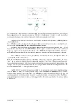
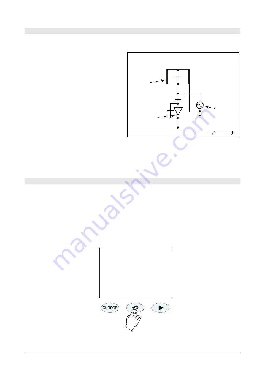
The electric calibration, using the partition of charge injected into the microphone preamplifi-
er in “charge amplifier” configuration (Capacitive Transducer Calibration), even if it
cannot com-
pletely replace the acoustic calibration
,
provides however a useful means to keep un-
der control the instrument drifts, microphone
included. The figure on the right shows the
diagram of the CTC technique consisting in
sending an electrical signal to the preamplifi-
er through a high stability capacitor, so that
the output signal does not depend only on
amplification, but also on the microphone ca-
pacity. Many of the microphone malfunctions
reflect in a capacity drift identifiable by
means of this calibration technique. The elec-
tric calibration uses as a reference the result
of the last acoustic calibration, and according
to it corrects any possible drift of the instru-
ment. The electric calibration adjusts the acoustic response of the microphone-sound level meter
chain, both for wideband channels, and for those with a constant percentage bandwidth. In case of
continuous instrument drifts, it is suggested to carry out an acoustic calibration to verify that there
are no other problems both in instrument and microphone.
Operating Procedure
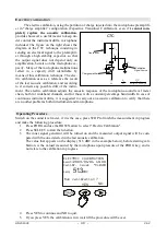
Switch on the sound level meter, if it is the case, press STOP to finish the measurement in progress
and make the following procedure:
1.
Press PROG and use the DOWN arrow to select "Electric Calibration".
2.
Press SELECT to start the function.
3.
The inner signal generator will be turned on and the measured output signal will be com-
pared with the one detected in the last acoustic calibration.
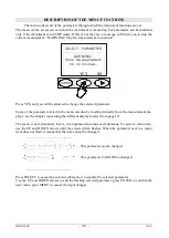
The value that appears on the display (51.3 dBC in the example below), before starting cali-
bration, is the valued measured by the microphone upon pressure of the PROG key, and is
not relate to the calibration in progress.
ELECTRIC CALIBRATION
Last:2003/01/01 10.00
Calibr. level 94.0dB
Leq
dBC
51.3
YES
NO
Run calibration
?
4.
Press YES to continue and NO to quit.
5.
If you press YES, the calibration is run: wait till the procedure will be over.
C
m
C
c
C
f
V
0
Calibration
Signal Source
Transducer
CTC
-A
Charge amplifier
C
b
V
i
V
0
V
i
C
c
C
m
+ C
b
+ C
c
= -
C
b
C
f
Summary of Contents for DeltaOHM HD2010UC
Page 2: ...HD2010UC 2 V4 2 ...
Page 129: ...HD2010UC 129 V4 2 NOTES ...
Page 130: ...HD2010UC 130 V4 2 NOTES ...
Page 131: ......

