background image


LPPYRA12 

-   17   -


V2.5


6


RS485 MODBUS-RTU OUTPUT 

Before connecting the pyranometer to the RS485 network, an address must be assigned 
and the communication parameters must be set, if different from the factory preset. 

6.1


S

ETTING THE COMMUNICATION PARAMETERS


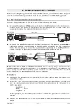
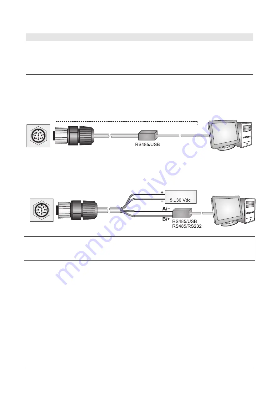
Connect the pyranometer to the PC in one of the following two ways: 

A.


By using the optional 

CP24

 cable, with built-in RS485/USB converter. In this con-

nection  mode,  the  sensor  is  powered  by  the  PC  USB  port.  To  use  the  cable,  it  is 
necessary to install the related USB drivers in the PC. 


B.


By  using  the  supplied  8-pole  M12  female  connector  or  the  optional 

CPM12-8D…


cable  and  a  generic  RS485/USB  or  RS485/RS232  converter.  In  this  connection 
mode,  it  is  necessary  to  power  the  pyranometer  separately.  If  a  RS485/USB  con-
verter is used, it is necessary to install the related USB drivers in the PC. 


N

OTES  ON  THE  INSTALLATION  OF  UNSIGNED  USB  DRIVER

before installing unsigned USB driver into 

operating  systems  starting  from  Windows  7,  it  is  necessary  to  restart  the  PC  by  disabling  the 
driver  signing  request.  If  the  operating  system  is  64-bit,  even  after  installation  the  request  of 
driver signing have to be disabled each time the PC is restarted. 

Procedure: 

1.


Start with the pyranometer not powered (if the CP24 cable is used, disconnect one 
end of the cable). 

2.


In the PC, start a serial communication program. Set the Baud Rate to 57600 and 
set the communication parameters as follows (the pyranometer is connected to a 
COM type port): 

Data Bits:  8 
Parity: 

 None 

Stop Bits:  2 

In  the  program,  set  the  COM  port  number  to  which  the  pyranometer  will  be  con-
nected. 

3.


Switch  the  pyranometer  on  (if  the  CP24  cable  is  used,  connect  both  ends  of  the 
cable). 

Power supply 

or 

CPM12-8D… cable 

Red 

Blue 
Brown 

White 

Pyranometer 

connector 

CP24 cable 

Pyranometer 

connector 

Summary of Contents for DeltaOHM LPPYRA12

Page 1: ...Operating manual Pyranometer LPPYRA12 www deltaohm com English Keep for future reference ...

Page 2: ...CONNECTIONS 12 4 4 LPPYRA12S CONNECTIONS 13 4 5 LPPYRA12S12 CONNECTIONS 14 4 6 LPPYRA12ACS 4 CONNECTIONS 15 5 MEASUREMENT IN THE MODELS WITH ANALOG OUTPUT 16 5 1 LPPYRA12 16 5 2 LPPYRA12AC S 4 16 5 3 LPPYRA12AV 4 16 6 RS485 MODBUS RTU OUTPUT 17 6 1 SETTING THE COMMUNICATION PARAMETERS 17 6 2 READING THE MEASURES WITH THE MODBUS RTU PROTOCOL 19 7 SDI 12 OUTPUT 20 8 MEASUREMENT CORRECTION 24 9 MAINT...

Page 3: ... m2 LPPYRA12AC4 ACTIVE with 4 20 mA CURRENT output 0 4000 W m2 LPPYRA12ACS ACTIVE with 4 20 mA CURRENT output 0 2000 W m2 and RS485 Modbus RTU output LPPYRA12ACS4 ACTIVE with 4 20 mA CURRENT output 0 4000 W m2 and RS485 Modbus RTU output LPPYRA12AV ACTIVE with 0 1 or 0 5 or 0 10 V VOLTAGE output 0 2000 W m2 to be defined when ordering LPPYRA12AV4 ACTIVE with 0 1 or 0 5 or 0 10 V VOLTAGE output 0 4...

Page 4: ...a proper thermal insulation from the wind and reduce the sensitivity to thermal irradiance LPPYRA12 is equipped with two concentric domes having 50 mm and 32 mm outer diameter The domes protect the thermopile from the dust which might change spectral sensitivity if it lies on the black surface The shadow ring prevents the direct solar radiation to reach the sensor the whole day long so that only t...

Page 5: ... a coin 3 Remove the cartridge perforated cap 4 Open the sachet containing silica gel supplied with the pyranometer 5 Fill the cartridge with the silica gel crystals 6 Close the cartridge with its own cap paying attention that the sealing O ring be properly positioned 7 Screw the cartridge to the pyranometer body using a coin 8 Check that the cartridge is screwed tightly if not silica gel life wil...

Page 6: ...ews that allow adjusting the pyranometer inclination 3 1 MOUNTING THE SHADOW RING LPPYRA12 is made up of two parts the pyranometer and the shadow ring 301 mm Ø 570 m m Ø 596 m m 5 3 m m 3 4 0 m m m a x Fig 3 2 LPPYRA12 dimensions and description To make the transport easier the shadow ring is disassembled in the following pieces Base composed of three spokes Shadow ring with L profile Sliding bars...

Page 7: ...e steps first align the shadow ring along the North South axis and then adjust the ring tilt Fig 3 3 positioning the instrument Aligning the shadow ring along the North South axis 1 Wait for solar midday 2 On the goniometer where the pyranometer is mounted there is a groove rotate the shadow ring base until the sunbeams pass through the groove from both sides of the goniometer Fig 3 4 shadow ring ...

Page 8: ...lel to the ground Use the levelling device on the pyranometer body 5 If the operations have been carried out properly the shadow ring axis will be paral lel to the earth axis By now you just have to adjust the height of the sliding bars loosening the locking screws until the pyranometer big dome appears completely in the shade To confirm that installation has been performed correctly you can compa...

Page 9: ... to be set on the sliding bars mm if installed in the Southern hemisphere 23 26 21 12 101 121 22 10 1 3 12 96 116 20 21 1 22 11 87 107 18 29 1 13 11 77 97 16 5 2 6 11 68 88 14 11 2 31 10 58 78 12 17 2 25 10 49 69 10 23 2 19 10 39 59 8 28 2 14 10 29 49 6 5 3 8 10 19 39 4 10 3 3 10 10 30 2 15 3 28 9 0 20 0 21 3 23 9 10 10 2 26 3 18 9 20 0 4 31 3 12 9 30 10 6 5 4 6 9 39 19 8 10 4 2 9 49 29 10 16 4 27...

Page 10: ...et on the sliding bars mm if installed in the Southern hemisphere 23 26 21 12 92 130 22 10 1 3 12 87 125 20 21 1 22 11 78 116 18 29 1 13 11 68 106 16 5 2 6 11 59 97 14 11 2 31 10 49 87 12 17 2 25 10 40 78 10 23 2 19 10 30 68 8 28 2 14 10 20 58 6 5 3 8 10 10 48 4 10 3 3 10 1 39 2 15 3 28 9 9 29 0 21 3 23 9 19 19 2 26 3 18 9 29 9 4 31 3 12 9 39 1 6 5 4 6 9 48 10 8 10 4 2 9 58 20 10 16 4 27 8 68 30 1...

Page 11: ...LPPYRA12AV 4 the housing is not connected to the connector Inside the housing there is a surge protector connected between the housing itself and the electronic circuit powered models or the ca ble shield passive model Grounding the housing allows the correct protection function in particular against lightning of the surge pro tector 4 1 LPPYRA12 CONNECTIONS The pyranometer LPPYRA12 is passive and...

Page 12: ... on the ordered output and requires external power supply 10 30 Vdc for 0 1 V and 0 5 V outputs 15 30 Vdc for 0 10 V output It is to be connected to a power supply and an instrument with voltage input as shown in fig 4 3 The load resistance of the instrument reading the signal must be 100 kΩ Connector Function Color 1 Output positive Vout Red 2 Output negative Power supply negative GND Blue 3 Powe...

Page 13: ...485 A Brown 5 RS485 B White 6 Housing Cable shield SH Black 7 Not connected 8 Not connected Shield Shield Lmax 1200m B A 1 2 3 4 5 6 7 8 B A SGND Vdc GND GND Vdc A B SH R 220 T Ω R 220 T Ω Fig 4 4 LPPYRA12S connections Before connecting the pyranometer to the RS485 network set the address and the communication parameters if different from the factory preset see chapter 6 Power supply CPM12 8D cabl...

Page 14: ... 7 8 GND Vdc SDI 12 SDI 12 BUS Vdc GND SH Fig 4 5 LPPYRA12S12 connections More SDI 12 sensors can be connected in parallel The distance between a sensor and the acquisition system data logger should not exceed 60 m Due to its low power consumption 200 µA LPPYRA12S12 is particularly suitable for battery solar panel powered data acquisition systems Before connecting the instrument to an SDI 12 netwo...

Page 15: ...r 1 Power supply negative GND Blue 2 Power supply positive Vdc Red 3 Digital and analog ground SGND Black 4 RS485 A Brown 5 RS485 B White 6 Housing Cable shield SH Black thick wire 7 Analog output positive AOUT Green 8 Not connected R 220 T Ω Shield Shield Lmax 1200m B A 1 2 3 4 5 6 7 8 B A SGND Vdc GND 4 20 mA AOUT SGND GND Vdc A B SH R 220 T Ω Fig 4 6 LPPYRA12ACS 4 connections Before connecting ...

Page 16: ...ance range The irradiance Ee is obtained by measuring with a multimeter the current Iout absorbed by the sensor and applying the following formula Ee 125 Iout 4 if f s 2000 W m2 Ee 250 Iout 4 if f s 4000 W m2 where Ee is the irradiance expressed in W m2 Iout is the current expressed in mA absorbed by the pyranometer 5 3 LPPYRA12AV 4 The output signal 0 1 V 0 5 V or 0 10 V depending on the version ...

Page 17: ...ry to install the related USB drivers in the PC NOTES ON THE INSTALLATION OF UNSIGNED USB DRIVER before installing unsigned USB driver into operating systems starting from Windows 7 it is necessary to restart the PC by disabling the driver signing request If the operating system is 64 bit even after installation the request of driver signing have to be disabled each time the PC is restarted Proced...

Page 18: ...ata bits no parity 2 stop bits n 2 8 E 1 8 data bits even parity 1 stop bit n 3 8 E 2 8 data bits even parity 2 stop bits n 4 8 O 1 8 data bits odd parity 1 stop bit n 5 8 O 2 8 data bits odd parity 2 stop bits Preset on 2 8 E 1 CMWn Set receiving mode after RS485 transmission n 0 Violate protocol and go in Rx mode right after Tx n 1 Respect protocol and wait 3 5 characters after Tx Preset on 1 Re...

Page 19: ...4 3 Status register bit0 1 solar radiation measurement error bit2 1 configuration data error bit3 1 program memory error 16 bit Integer 5 4 Average values of the last 4 measurements 16 bit Integer 6 5 Signal generated by the sensor in µV 10 e g 816 means 8160 µV the resolution is 10 µV 16 bit Integer Note Register address Register number 1 as defined in the Modbus standard OPERATING MODE the pyran...

Page 20: ...wing table The following table reports the SDI 12 commands available For consistency with SDI 12 standard documentation the instrument address is indicated in the table with the letter a SDI 12 Commands Command Instrument reply Description a a CR LF Verifies the presence of the instrument aI allccccccccmmmmmmvvvssssssss CR LF with a address of the instrument 1 character ll SDI 12 compliant version...

Page 21: ...nal temperature in the set unit of measurement default C Example of response 0 0 228 7 3 294 25 0 probe address 0 content of the status register 0 irradiance 228 7 W m2 signal internal level 3 294 mV internal temperature 25 0 C Note the status register normally contains zero a value different from zero indicates an error condi tion Reads the measurement Irradiance and internal temperature aM1 aC1 ...

Page 22: ... execute the measurement aD0 a v v CR LF with v v signal internal level in mV Example of response 0 3 294 probe address 0 signal internal level 3 294 mV Reads the measurement In addition to the above mentioned commands the sensor also implements the corre sponding commands with CRC that require to add a 3 character CRC code at the end of the reply before CR LF The format of these commands is obtai...

Page 23: ...Send the command aXSCAL USER ON note a instrument address 2 Send the command aXSCFD to set C or aXSCFE to set F 3 Send the command aXSCAL END For more information about the SDI 12 protocol visit the website www sdi 12 org ...

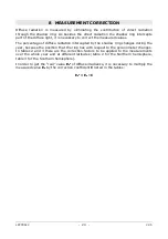
Page 24: ...tion intercepted by the shadow ring changes during the year because the position that the ring has with respect to the pyranometer changes In tables 2 and 3 there are the correction factors to be applied to the measurements over the whole year and at different latitudes table 2 for the Northern hemisphere table 3 for the Southern hemisphere In order to get the real value Ee v of diffuse irradiance...

Page 25: ...1 11 1 11 1 12 1 12 1 12 1 13 1 13 1 13 1 12 1 12 20 1 10 1 11 1 11 1 12 1 12 1 12 1 12 1 12 1 12 1 12 22 1 10 1 10 1 11 1 11 1 11 1 12 1 12 1 12 1 12 1 12 23 1 09 1 10 1 10 1 11 1 11 1 11 1 12 1 12 1 12 1 12 Solar declination Northern latitude 50 55 60 65 70 75 80 85 90 23 1 02 1 01 1 00 1 00 1 00 1 00 1 00 1 00 1 00 22 1 02 1 02 1 01 1 00 1 00 1 00 1 00 1 00 1 00 20 1 03 1 02 1 01 1 00 1 00 1 00...

Page 26: ...1 11 1 11 1 12 1 12 1 12 1 13 1 13 1 13 1 12 1 12 20 1 10 1 11 1 11 1 12 1 12 1 12 1 12 1 12 1 12 1 12 22 1 10 1 10 1 11 1 11 1 11 1 12 1 12 1 12 1 12 1 12 23 1 09 1 10 1 10 1 11 1 11 1 11 1 12 1 12 1 12 1 12 Solar declination Southern latitude 50 55 60 65 70 75 80 85 90 23 1 02 1 01 1 00 1 00 1 00 1 00 1 00 1 00 1 00 22 1 02 1 02 1 01 1 00 1 00 1 00 1 00 1 00 1 00 20 1 03 1 02 1 01 1 00 1 00 1 00...

Page 27: ...In this case the performed reading is highly over estimated To minimize the condensation the pyranometer is provided with a cartridge containing dessicant material silica gel The efficiency of the silica gel crys tals decreases over time while absorbing humidity Silica gel crystals are efficient when their color is yellow while they turn white translucent as soon as they lose their efficiency Read...

Page 28: ... output 7 30 Vdc SDI 12 output Consumption 200 µA for the version LPPYRA12S12 Connection 4 or 8 pole M12 connector depending on the model Dimensions Fig 3 2 Weight 6 8 kg approx pyranometer shadow ring Accuracy of levelling device 0 1 Protection degree IP 67 MTBF 10 years Technical Specifications According to ISO 9060 2018 Classification Spectrally Flat Class B Response time 95 10 s Zero offset a ...
Page 29: ... well as the specific measures described in this manual are followed The instrument proper operation and operating safety can be ensured only in the cli matic conditions specified in this manual Do not use the instruments in places where there are Corrosive or flammable gases Direct vibrations or shocks to the instrument High intensity electromagnetic fields static electricity User obligations The...

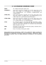
Page 30: ...n wires on the other end Length 2 m CPM12 8DA 2 5 m CPM12 8DA 5 or 10 m CPM12 8DA 10 For LPPYRA12ACS 4 CP24 PC connecting cable for the RS485 MODBUS parameters configu ration of the LPPYRA S pyranometers With built in RS485 USB converter 8 pole M12 connector on instrument side and A type USB connector on PC side LPSG Cartridge to contain desiccant silica gel crystals complete with O ring and cap s...

Page 31: ......

Page 32: ...ranty included in the manual of the product For any dispute the competent court is the Court of Padua The Italian law and the Convention on Contracts for the International Sales of Goods apply TECHNICAL INFORMATION The quality level of our instruments is the result of the continuous product development This may lead to differences between the information reported in the manual and the instrument y...

Reviews: