background image

E40.0.5X.6C-01 

Operating Manual EASY

LOG

 80IMP… 

page 6 of 16 

4. Display and control elements 

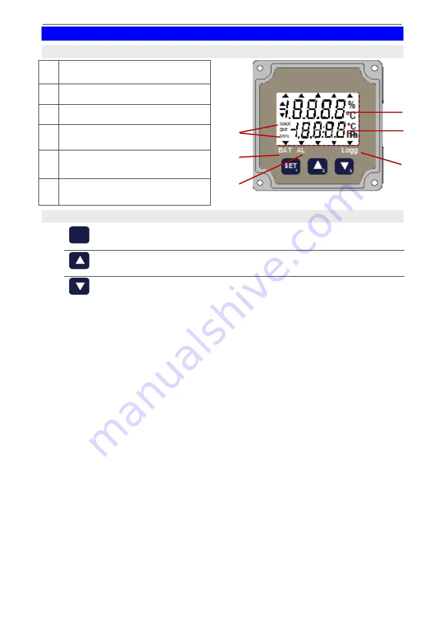
4.1  Display 

  Main display 


  Secondary display 


  Display element for max / min 


  Logg: indicates that logger is 

recording 


  BAT:  signals weak battery 

(see chapter 8).


  AL:   signals an alarm state at min-

imum one channel  




4.2  Function of the buttons (brief description) 


SET


(button 1)


• 

call menu


Arrow key 

UP


(button 2)


• 

call / delete max-value


Arrow key 

DOWN


(button 3)


• 

call / delete min-value


SET

1

2

3

Summary of Contents for GREISINGER EASYLOG 80IMP Series

Page 1: ...NY Tel 49 9402 9383 0 info greisinger de www greisinger de Installation and operating manual Data logger for impulse from version 8 0 EASYLOG 80IMP Please read these instructions carefully before use...

Page 2: ...perating possibilities at the device min max value memory 8 6 2 Operating possibilities at the device signal edge selection 8 6 3 Operating possibilities at the device logger operation 9 6 4 Operating...

Page 3: ...for damages and consequential damages are voided with misuse disregard of this operating manual assignment of inadequately qualified technical personnel and arbitrary modifications of the product 2 2...

Page 4: ...only be guaranteed if the device is not subjected to any other climatic conditions than those stated under Specification 5 When connecting the device to other devices e g PC the interconnection has t...

Page 5: ...wer consumption is at its minimum When there is a communication with the software for the first time the EASYLOG leaves the sleep mode and Stop is displayed Then the device is ready for operation Note...

Page 6: ...lay Display element for max min Logg indicates that logger is recording BAT signals weak battery see chapter 8 AL signals an alarm state at min imum one channel 4 2 Function of the buttons brief descr...

Page 7: ...tching contact Connecting diagram Example connecting a transducer with npn output Switch ing contact transducer power supply for transducer 5 3 Connection an EASYLOG 80IMP T TTL signal input active si...

Page 8: ...lay by pushing the button again Delete min value Push button for about 5 seconds CLr is displayed and the min values of all measuring channels are deleted 6 2 Operating possibilities at the device sig...

Page 9: ...tart recording Push button for about 5 seconds The main display shows run The secondary display shows no To start recording select YES with the arrow keys button or and verify with Note If no key is p...

Page 10: ...ded to change the configuration settings With that software the following adjustment are additionally possible adjustment of display range position of decimal point and the display unit adjustment of...

Page 11: ...r status messages are dis played STOP The EASYLOG recording has been stopped The logger memory is empty Note At this state the power consumption is at its minimum HOLD The EASYLOG recording has been h...

Page 12: ...to the manufacturer for repair 8 4 Alarm and error messages The following messages correspond to a particular measuring channel and are dis played accordingly ALARM LOW The measured value is below the...

Page 13: ...more than 25 units is given in the software used Resolution 1 digit Accuracy 0 1 FS at nominal temperature Display two 4 digit LCD displays about 7 and 5 8 mm high Interface EASYBus Busload equals to...

Page 14: ...s Applied harmonized standards EN 50581 2012 EN 61326 1 2013 emissions level class B emi immunity according to table 1 additional error 1 Note When connecting long leads adequate safety measures again...

Page 15: ...figurator Problem The alarm settings cannot be changed Possible reason The logger has still saved data Remedy Stop logger as recommended by the software delete data Problem A error message is displaye...

Page 16: ...ction diagram for a relay with self induction recuperation diode b Connection information for GR 10 GNR 10 or GNR 232 A GND to be connected to terminal 11 of the GNR NPN to be connected to terminal 10...

Reviews: