E42.X.1X.6C-02
Operating Manual GIA 0420 N / GIA 010 N
page 4 of 10
5
Electric connection
The GIA ... N is connected via screw-type/plug-in terminals on the rear side.
General Note:
Screw-type/plug-in terminals have to be mounted while they are still loose and plug them in only
afterwards. Soldering lands may be damaged in case of improper assembly of already plugged
terminals.
Please use applicable screwdriver and do not forcibly tighten the screws.
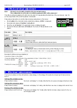
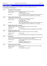
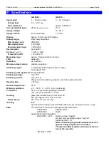
Supply voltage:
GIA 0420 N
device takes power from measuring current
GIA 010 N
12 ... 28 V or according device declaration
Electric connection and commissioning of the device must be carried out by trained and skilled personnel.
Wrong connection may lead to the destruction of the display device, in which case we cannot assume any warranty!
! Mind for the GIA 0420 … the maximum input current rating of 40mA under any circumstances !
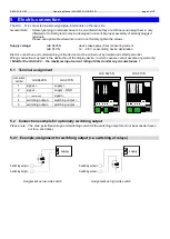
5.1 Terminal assignment
GIA 0420 N
GIA 010 N
connection
number
GIA 0420 N
GIA 010 N
1
2
signal -
supply -, GND
3
---
(inexistent)
4
switching
switching
5
switching output -
switching output -
5.2 Connection example for optionally switching output
Please note: The max. permitted voltage and switching current of the switching output must not be exceeded (even
not for a short time).
5.2.1 Example assignment for switching output (i.e. switching of relays)
Assignment as low-side switch
Assignment as high-side switch
O
utpu
t +
Inpu
t mA
-
Inpu
t mA
+
O
utpu
t -
T1
T3
T2
5 4
2 1
3
n.c
.
O
utpu
t +
Inpu
t mA
-
Inpu
t mA
+
O
utpu
t -
T1
T3
T2
5 4
2 1
3
n.c
.
O
utpu
t +
G
N
D
/ -
U
v
+
U
v
O
utpu
t -
0 -
10
V
Switching
Switching output -
supply
supply
Switching
Switching output -


