E42.X.1X.6C-02
Operating Manual GIA 0420 N / GIA 010 N
page 5 of 10
6
Configuration
Note:
The device can be ESD sensitive at the area of the buttons.
The configuration must be done considering adequate ESD safety measures!
Please note: measuring current should be at least 4 mA during configuration of a GIA 0420 N!
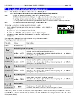
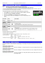
Follow these instructions to configure the device:
Press
button 2
for 2 seconds during actual value display, „
dP
“ is displayed.
Set parameter value with
button 2
and
button 3
.
Save the set with
button 1
, the parameter name is displayed again.
Proceed to the next parameter with
button 1
, the name of that parameter is dis-
played.
If there is no key pressed within 60 seconds the configuration is cancelled.
The settings already entered are lost.
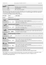
Parameter
Value
Description
Button 1
Button 2 and 3
DP
Position of decimal point
----
Max. display range: -1999
… 9999
---.-
Max. display range: -199,9
… 999,9
--.--
Max. display range: -19,99
… 99,99
-.---
Max. display range: -1,999
… 9,999
D,.LO
Lower display range limit (display low)
-1999
...
9999
This value is displayed for input signal = 4mA.
D,.X,
Upper display range limit (display high)
-1999
...
9999
This value is displayed for input signal = 20mA.
L,
(Measuring range) limit
OFF
deactivated:
Exceeding of the measuring range limit is tolerable as long as value is within
measuring range (p.r.t. note).
ON.ER
active,
(display error):
The measuring range limit is exactly bounded by the input signal.
When exceeding or short falling the input signal the device will display an error
message.
ON.RG
active,
(display measuring range limit):
The measuring range limit is exactly bounded by the input signal.
When exceeding or short-falling the input signal the device will display the se-
lected lower/upper display value.
e.g. humidity: when shortfalling or exceeding, the device will display 0% or 100%.
Note:
When exceeding the measuring range, the device will always display an error message (.Err.1. or .Err.2.)
independent of the current limit settings
.
The measuring range is from approx
3,7 and 20,8 mA respective 10.5 V
(a falling below 0V will not detected)
.
FILT
Filter
OFF
Filter deactivated
0. 1
...
2.0
Filter active:
Prevents “jumping” of the last digit and filters short noise pulses.
Higher numbers imply stronger filtering
Attention: this causes higher response times of the switching functions!
T1
T3
T2
5 4
2 1
3


