54
P U S H - T O - O P E N
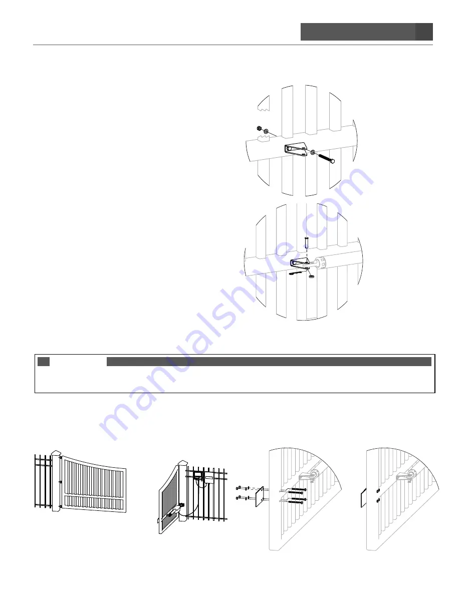
F. Align the innermost hole of the estate and front mount brackets and insert (1) M8 x 65mm flat washer,
and (1) M8 nylon locknut through both holes and tighten to secure the bracket to the gate.
YOUR FRONT
MOUNT AND ESTATE BRACKET SHOULD NOW BE ATTACHED AND SECURED TO THE GATE.
G. Align and attach arm of operator to the
secured front mount bracket, as shown
below.
Make sure all parts installed
during installation are tightened down.
STEP 15.
IF ADDING A SECOND GATE OPERATOR REPEAT STEPS 1 – 14 (SKIP STEPS 7 & 8)
NOTE
For second operator you will need to dig a trench and use pvc conduit to put second operator power cables thru to connect
to the control box (2nd Operator Terminals) on the opposite side of the driveway.
STEP 16.
INSTALL THE POSITIVE STOP PLATE.
Use the supplied Positive Stop Plate and hardware to install the Positive Stop Plate on the
INSIDE OF THE FIRST
OPERATOR GATE as shown in the image below.
STEP 17. Proceed to Programming the Closed Limit Switch Step 18.
Summary of Contents for Ghost Pro LDM2
Page 6: ...6 B L A N K P A G E ...
Page 19: ...19 B L A N K P A G E G h o s t C o n t r o l s 2 0 2 0 ...
Page 67: ......


