background image

GHOST


User Manual Status 04/2009 //  Spec 2010


6.34 


• 

Rims with wear indicators: 

- Visual 

inspection 

• 

Rims without wear indicators: 

-  Visual inspection  

-  Finger nail test: Run your finger nail across the rim flank. You should 

not feel scratches or scores. 

• 

If the wear indicator is no longer visible or the rims exhibit visible scratches 
or scores that can be felt with your finger nail, the rim must be replaced. 

2. 

Check the rims for wobble: 

• 

Pick up the bike and rotate the front and rear wheel in turn.  

• 

Pay attention to the clearance between rim and brake blocks,


on bikes with 

disc brakes to the distance between rim and frame strut or fork blade.  
The maximum permissible deviation per revolution is 2 mm.  

3. 

Inspect the rims for soiling, in particular for oil or grease. 
Soiled rims must be cleaned immediately (see chapter 11). 

6.1.3 

Check the tyres 

1. 

Check the valve position: 


Does not apply to tubeless tyres. 


Danger of personal injury and material damage! 

If the valves are crooked, the valve foot may tear off while riding resulting in a 
sudden loss of pressure in the tyre. This can lead to dangerous riding 
situations, falls, accidents and material damage. 


Have the positioning of the tyre on the rim corrected by your dealer. 
You can carry out this work yourself if you are familiar with the removal 
and installation of the wheels (see chapter 10.1) and the replacement of 
tyres and tubes. 


• 

If necessary, remove the valve nut.  

• 

Check the valve position: 
The valves must be pointing towards the middle of the wheel.  

Summary of Contents for Bike

Page 1: ...User Manual for GHOST Bikes ...

Page 2: ...risks 2 14 2 2 1 Hazards due to incorrect final assembly 2 14 2 2 2 Hazards due to improper use 2 14 2 3 Disposal 2 15 3 Scope of Supply Technical Data 3 16 3 1 Scope of supply 3 16 3 2 Technical data 3 16 4 Design and Function 4 17 4 1 Categories 4 17 4 2 Mountain bike AMR AMR Plus AMR Square ASX ERT FR Northshore 4X DIRT RT HTX MISS MISS AMR MISS RT SE 4 17 4 3 Cross bike CROSS Series 4 21 4 4 S...

Page 3: ...in 6 52 6 10 Inspect the lighting system 6 53 6 11 Inspect the luggage rack 6 53 6 12 Inspect the mudguards 6 53 6 13 Check other points 6 54 7 Adjusting and Operating the Bike 7 56 7 1 Adjust the adjustable handlebar stem option 7 56 7 2 Adjust the saddle position 7 56 7 3 Adjust the saddle height 7 58 7 4 Adjust the spring fork 7 58 7 5 Adjust the rear wheel suspension 7 59 7 6 Operating the gea...

Page 4: ...0 92 10 1 1 All categories except RACE Series 10 93 10 1 2 RACE Series 10 108 10 2 Install and remove saddle post with saddle 10 115 11 Cleaning and Maintaining the bike 11 123 12 Storing the Bike for Prolonged Periods 12 127 13 Warranty Guarantee 13 128 General 13 128 Stability guarantee on frames from model year 2008 13 128 14 Delivery Certificate 14 129 15 Imprint 15 131 ...

Page 5: ...mentally friendly and sporting means of travel with which you will have a great deal of pleasure while at the same time doing something for your health and fitness Even after providing advice and carrying out the final assembly your bike dealer is still very important to you He is your contact person for maintenance inspections modifications and repairs of all kinds Should you have any questions a...

Page 6: ...omprehensible please consult your dealer Danger of personal injury and material damage User manual for children and youths This user manual is directed at the guardians of the children and youths who use this bike If the children and or youths under your guardianship fail to observe the information in this user manual this can result in dangerous riding situations falls accidents and material dama...

Page 7: ...ting bike components it is not possible to produce a generally applicable user manual Therefore always observe also the information in the component user manuals supplied with the bike This information takes priority in all cases over deviating information in the following text 1 2 Conventions 1 2 1 Symbols Note Draws attention to information of particular importance Warning Draws attention to the...

Page 8: ...initions of terms Dealer approved workshop In Germany The term dealer and or approved workshop as used in this user manual refers to dealers with qualifications as two wheeler mechanic and or bike mechanic who are authorised by the Chamber of Commerce to operate an approved workshop These must also be authorised by the manufacturer of this bike to inspect and confirm the correct final assembly and...

Page 9: ... of measure for air pressure inch abbreviated to English or American unit of length often used for frame and wheel sizes 1 2 54 cm psi pounds per square inch English or American unit for pressure 1 psi 0 069 bar Nm Newton metre unit of measure for tightening torque Hand force The force that an average person can apply with moderate effort using one hand ...

Page 10: ...e rider must be physically and mentally capable of using this bike on public roads as long as the bike is approved for such use Children and youths must be able to operate the bike safely The operating elements e g brake levers must be suitable for children s hands 2 1 2 How are you allowed to ride your bike Danger of personal injury and material damage Sit on the saddle or ride standing up on the...

Page 11: ... specially marked tracks at high to very high speed 4 X and dirt Tracks similar to those for BMX Your safety on these streets and paths depends on your speed The higher your speed the greater your risk Note that all streets and paths may be damaged and or have obstacles that can impair your safety and damage your bike In such areas ride particularly slowly and carefully If necessary push or carry ...

Page 12: ...ns high speed riding over edges street steps ground waves etc Use of your bike in the bike park for sporting applications where there is always a risk of accidents Adapt the use of your bike to your riding skills 2 1 4 In what condition must your bike be for riding Your new bike is sports equipment and may only be used on public roads and paths when fitted with the accessories stipulated in your l...

Page 13: ...number For correct attachment of these parts to your bike please consult your dealer Chain sprocket guard 2 1 5 What must you not do Danger of personal injury and material damage Many cyclists like to modify their bikes and adapt them to their personal wishes Saddle handlebars pedals brakes tyres suspension elements there are innumerable possibilities for subsequent modification of your bike Work ...

Page 14: ... final assembly of this bike can lead to dangerous riding situations falls accidents and material damage Have the correct final assembly and the adjustment of the correct seating position for you confirmed by your dealer Please use the preprinted form in this user manual 2 2 2 Hazards due to improper use Danger of personal injury and material damage Failure to observe the information in this user ...

Page 15: ...ur dealer if you have any questions Increased loads extend your braking distance Note that some items of clothing and or the use of a backpack can hinder your mobility Do not exceed the admissible total weight of your bike see chapter 3 2 Determine the admissible total weight by picking up your bike with the complete load and standing in your complete riding gear together with your bike on calibra...

Page 16: ...ease consult your dealer Component Manufacturer Model Type Connection Type of connection Tightening torque Nm Saddle post GID fixed Saddle clamp One bolt 17 20 Saddle post GHOST BMX CroMo fixed Saddle clamp Two bolts 5 6 Saddle post Ritchey fixed Saddle clamp Two bolts 14 16 Saddle post Syncros fixed Saddle clamp Two bolts 14 16 Saddle post GID fixed Saddle clamp Two bolts 14 16 Saddle post GID sp...

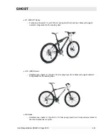
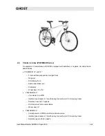
Page 17: ...DIRT RT HTX MISS MISS AMR MISS RT SE Cross bike CROSS Street RACE SPEEDLINE Trekking bike TR Children s bikes POWERKID You can find the category of your bike in the BIKE SERVICE CARD at the end of this user manual 4 2 Mountain bike AMR AMR Plus AMR Square ASX ERT FR Northshore 4X DIRT RT HTX MISS MISS AMR MISS RT SE No equipment in accordance with StVZO equipped with dérailleur rim brakes or disc ...

Page 18: ... properties ERT Series Fullies see chapter 4 7 2 with 100 160 mm spring travel front and 160 mm spring travel rear The main focus here is on the downhill properties but is also suitable for uphill riding CAUTION Corresponding skill and experience are preconditions for the use of this sports bike FR Northshore Series Fullies see chapter 4 7 2 with 180 mm spring travel front and rear The main focus ...

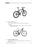
Page 19: ...ardtails see chapter 4 7 2 with 100 mm spring travel front The main focus here is on the suitability for the bike park and for jumping Equipment as for mountain bike but some models with only one brake without gears or with gears only for the rear sprocket cassette CAUTION Corresponding skill and experience are preconditions for the use of this sports bike ...

Page 20: ...ikes with weight oriented configuration for the sporting rider HTX MISS Series Hardtails see chapter 4 7 2 with 100 mm spring travel front Bikes with weight oriented configuration for the sporting rider SE Series Hardtails see chapter 4 7 2 with 80 100 mm spring travel front Sturdy universal bikes for the tour oriented leisure cyclist ...

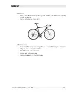
Page 21: ...heels with larger rim diameter of 622 mm 28 CROSS Series Hardtails see chapter 4 7 2 with 60 mm spring travel front Universal bikes for speedy progress on streets and paths 4 4 Street RACE SPEEDLINE Series No equipment in accordance with StVZO equipped with dérailleur rim brakes wheels with rim diameter 662 mm 28 ...

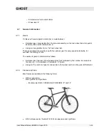
Page 22: ...pid sporting progress on the street Racing bike brakes see chapter 6 8 1 SPEEDLINE Series Bikes without frame suspension and rigid forks for rapid comfortable progress on the road Straight or mountain bike type handlebars Gear shift lever as for mountain bikes Rim brakes as for mountain bikes Slightly wider tyres than for the RACE Series ...

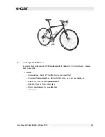
Page 23: ...illeur two rim or disc brakes luggage rack mudguards TR Series Hardtails see chapter 4 7 2 with 60 mm spring travel front Universal fully equipped bikes for comfortable progress on streets and paths Straight or mountain bike type handlebars Gear shift lever as for mountain bikes Rim or disc brakes as for mountain bikes Hub dynamo ...

Page 24: ...id forks No gears Rim brakes front Back pedal brake rear Stabilisers Wheel size 12 or 16 POWERKID 20 Very similar to a MTB Hardtail see chapter 4 7 2 with spring fork with up to 50 mm spring travel Derailleur rear with 7 speeds Rim brakes as for mountain bikes Wheel size 20 POWERKID 24 Corresponds to a MTB but with smaller wheel size Hardtail see chapter 4 7 2 with spring fork with up to 50 mm spr...

Page 25: ...with the optimum gear for every speed and simplify for example the climbing of hills The number of gears is determined as follows Derailleur gear Number of chainwheels at the front multiplied by the number of sprockets at the rear e g 3 chainwheels x 9 sprockets 27 gears Hub gear The number of gears corresponds to the highest number on the gear shift indicator 4 7 2 Frames and forks Bike frames ar...

Page 26: ...MR MISS RT HTX SE CROSS TR POWERKID 20 and 24 Full suspension With fork suspension and rear wheel suspension Model series AMR AMR Plus AMR Square ASX ERT FR Northshore RT MISS RT MISS AMR For full suspension bikes there are various suspension systems with different numbers of pivot joints ...

Page 27: ...nger of personal injury and material damage Impact loads that can occur if using the bike for other than the approved purpose see chapters 2 1 3 and 4 and collisions with flying stones can lead to invisible damage in the carbon fabric and or to delaminations separation of the bonded carbon layers Such prior damage together with the forces occurring during operation can cause carbon parts to sudden...

Page 28: ...away where it is not needed In this process individual prefabricated frame segments are joined together in turn until the frame has been completely assembled These high end products are produced manually Differences can therefore occur in the finish but these are not grounds for complaint 4 8 2 Proper handling of carbon parts 1 No additional parts may be attached to carbon tubes by means of clips ...

Page 29: ...his can result in damage to the bike frame Use on a loose roller without rigid clamping of the frame is permitted CAUTION This presupposes the necessary know how 7 Transport Take particular care when transporting bikes with carbon frames As with our bikes with aluminium frames they may only be transported inside motor vehicles Protect particularly the frame from contact with other parts Use blanke...

Page 30: ... operation Therefore anticipate longer braking distances for a certain time Disc brakes first have to be run in The full braking effects develops only after the running in period Observe the enclosed running in instructions from the brake manufacturer If your bike is equipped with optional clipless pedals that fix the shoe to the pedal Practice getting on and off your bike before use Clipless peda...

Page 31: ...r that your bike is not in the proper condition Ride your bike again only when it has been properly repaired by your dealer The parts described below are not installed on all bikes Some parts can also be installed later Check in chapter 4 and with the aid of the following illustrations which equipment your bike has Carry out the corresponding checks If you are not sure about anything or have any q...

Page 32: ... at right angles to the running direction The wheels must not move in their mounting The quick release lever must be closed see chapter 7 9 No cracking or grinding noises should be heard Contact your dealer if the inspection reveals faults of any kind 6 1 2 Check the wheel rims Danger of personal injury and material damage Worn rims and or extreme wobble can lead to dangerous riding situations fal...

Page 33: ...GHOST User Manual Status 04 2009 Spec 2010 6 33 Wear indicator Wear indicator Wear indicator 1 Check the rims for wear ...

Page 34: ... permissible deviation per revolution is 2 mm 3 Inspect the rims for soiling in particular for oil or grease Soiled rims must be cleaned immediately see chapter 11 6 1 3 Check the tyres 1 Check the valve position Does not apply to tubeless tyres Danger of personal injury and material damage If the valves are crooked the valve foot may tear off while riding resulting in a sudden loss of pressure in...

Page 35: ...the type of tyres on your bike Mountain bikes may be fitted with racing bike type tyres racing bikes with trekking tyres Rule of thumb Mountain bike tyres Tyre width more than 40 mm Trekking cross and fitness bike tyres Tyre width from 28 mm 40 mm Racing bike type tyres Tyre width less than 28 mm Contact your dealer if you are not sure which type of tyres is installed on your bike ...

Page 36: ... using the following table psi 30 40 50 60 70 80 90 100 110 120 130 140 bar 2 1 2 8 3 5 4 1 4 8 5 5 6 2 6 9 7 6 8 3 9 0 9 7 Refer to the rim or tyre manufacturer s specifications for the admissible tyre pressure The admissible tyre pressure is generally shown on the tyre flank Please consult your dealer The higher your body weight the higher the tyre inflation pressure has to be Check the tyre pre...

Page 37: ...rubber layer must not be visible There must be no visible blisters or cracks 4 Check the proper fitting of your tyres Raise the front and rear wheels alternately and turn the wheel by hand The tyre must run smoothly There must be no wobble or eccentricity 6 1 4 Check other points 1 Inspect your wheels for loose parts such as twigs fabric residues loose spoke reflectors etc If any loose parts are d...

Page 38: ...insertion depth of the saddle post Observe the instructions in chapter 7 3 If you have the necessary technical know how you can carry out this attachment yourself Observe the instructions in chapters 7 2 7 3 and 10 2 1 Check that the saddle and saddle post are securely fastened Try to twist the saddle and post in the frame by hand It must not be possible to twist the saddle and saddle post Try to ...

Page 39: ...ents If you discover damage to these parts or have any doubt about their integrity you must not use your bike again Contact an approved workshop immediately 1 Check the installation of handlebars and handlebar stem The handlebar stem must be parallel to the front wheel rim the handlebars at right angles to the stem In the case of a shaft handlebar stem the Max Stop or equivalent mark must not be v...

Page 40: ...lebar attachments 1 Check the secure attachment of the gear shift levers brake levers and handlebar grips A triathlon handlebar attachment and or bar ends horns may have been installed on your handlebars if these are permitted by the manufacturer Inspect these parts for proper attachment Clamp the front wheel between your legs Try to twist the brake levers with your hands ...

Page 41: ...s are correctly installed the handlebar grip test can be waived It must not be possible to move or twist any of the parts No cracking or grinding noises should be heard A bell if installed must be easily reached with finger or thumb it must not be possible to move the bell 6 5 Inspect the headset The headset is the mounting of the handlebar stem in the fork column 1 Check your headset It must be p...

Page 42: ... jerky movements The headset must not exhibit any backlash No cracking must be heard or felt Grinding noises are also not permitted Pick up the whole bike so that the rear wheel is higher than the front wheel Turn the front wheel to the side by means of a handlebar movement and release it again The front wheel must now move back independently into its original position The front wheel must not loc...

Page 43: ...refer also to the component manufacturer s operating instructions 6 8 Inspect the brakes Danger of personal injury and material damage A brake malfunction is a serious danger to safety Pay particular attention when checking the brake system During prolonged tours over several days the brake disc brake blocks and brake pads can become severely worn Always take replacement brake blocks and replaceme...

Page 44: ...kes applied Both wheels must remain locked 6 8 1 Check the rim brake with cable racing bike version Racing bike rim brake 1 Check the brake cables and their clamps The brake cables must not be damaged or corroded The brake cables of cable brakes must be clamped over their full width ...

Page 45: ...Try to pull the brakes from the fork front or frame rear with your hands The brakes must remain securely attached and the mountings must not exhibit any clearance 3 Check the position of the brake shoes When the brakes are applied the brake shoes must contact the rim flank with practically their whole surface area ...

Page 46: ...n when the brakes are not applied may the brake shoes touch the tyres 4 Check the wear of the brake blocks The brake blocks must not be worn beyond the wear indicator 5 Check that the brakes are centered The brake shoes must have the same distance to the rim on both sides ...

Page 47: ...version 1 Check the brake cables and their clamps The brake cables must not be damaged or corroded The brake cables of cable brakes must be clamped over their full width 2 Check the correct mounting and bolts of the whole brake system Try to pull the brakes out of the shoes with your hands ...

Page 48: ...of the brake shoes When the brakes are applied the brake shoes must contact the rim flank with practically their whole surface area In no position i e even when the brakes are not applied may the brake shoes touch the tyres 4 Check the wear of the brake blocks Unhook the brakes for the inspection see chapter 10 1 The brake blocks must not be worn beyond the wear indicator ...

Page 49: ...ole brake system Try to pull the brakes out of the shoes with your hands It must not be possible to pull the brakes blocks out of the shoes by hand A slight backlash is normal 2 Check your brake system for leaks Pull the respective brake lever with the bike at a standstill and hold the brake lever in this position Inspect the brake system from the brake lever along the lines up to the brakes No hy...

Page 50: ...akes are not applied may the brake shoes touch the tyres 4 Check the wear of the brake blocks The brake blocks must not be worn beyond the wear indicator 5 Check that the brakes are centered The brake shoes must have the same distance to the rim on both sides 6 8 4 Check the hydraulic disc brake Danger of personal injury and material damage Soiled brake discs can impair the braking effect Soiled b...

Page 51: ...hand The brake disc may only have a minimal lateral runout 5 Have the wear of the brake pads and brake disc checked in an approved workshop see also chapter 11 The brake pads must not be worn beyond the wear indicator The thickness of the brake disc must not be below the specified minimum For the minimum thickness please refer to the enclosed component instruction manual 6 Inspect the brake discs ...

Page 52: ...ection and observe the chainwheels and the sprocket assembly from above The chainwheels and sprockets must not have any lateral runout There must not be any foreign matter in any of the components Remove any such foreign matter if easily possible 2 Press the left hand pedal arm towards the chain run in the position shown You should not feel any bearing backlash No cracking or grinding noises shoul...

Page 53: ...ON OFF switch on the headlight Lift the front wheel Rotate the front wheel vigorously by hand The headlight and rear light must come on If installed check the function of the rear parking light 6 11 Inspect the luggage rack Danger of personal injury and material damage Loose or hanging parts of the luggage rack can jam the wheel and result in serious falls or accidents Use your bike again only whe...

Page 54: ...if folded down Always fold up the side stand before riding 1 Check your side stand if installed Carry out a visual inspection of the mounting bolt The side stand must be securely attached to the frame Always fold up the side stand before riding The stand must remain in this position even in the event of vibrations Danger of personal injury and material damage Incorrectly mounted or loose accessori...

Page 55: ...ersonal injury and material damage Damaged bike parts can have sharp edges that could cause injuries Check all parts of the bike with which you could come into contact while riding Have any damaged parts repaired or replaced immediately in an approved workshop ...

Page 56: ...ly when you have the necessary basic technical knowledge experience and appropriate tools 7 1 Adjust the adjustable handlebar stem option Some bikes are equipped with a handlebar stem that is adjustable in height and angle Have the adjustment carried out only in an approved workshop 7 2 Adjust the saddle position You saddle is secured with one or two clamping bolts For adjustment you need an Allen...

Page 57: ...ge with one another again correctly For saddle clamps with two bolts Turn the bolts alternately by a quarter to half a turn until the prescribed torque is reached For details of the prescribed tightening torque please refer to the table in chapter 3 2 Different tightening torques may be specified for some saddle posts If these are not listed in the table or directly on the saddle post please conta...

Page 58: ... wrench of the appropriate size for the saddle adjustment For a saddle clamp with quick release lever observe the instructions in chapter 7 9 1 Loosen the clamp as described in chapter 10 2 2 Move the saddle with saddle post to the desired position Observe the information on the insertion depth of the saddle post in chapter 10 2 3 Clamp the saddle post as described in chapter 10 2 7 4 Adjust the s...

Page 59: ... dealer If your total weight is outside this range have the appropriate spring elements for your weight installed by your dealer 7 5 Adjust the rear wheel suspension with full suspension bikes Fullies 1 For details of adjusting the spring damper element please refer to the component user manual from the manufacturer supplied with the bike Please consult your dealer 2 Adjust your spring damper elem...

Page 60: ...GHOST User Manual Status 04 2009 Spec 2010 7 60 Shimano Dual Control Shimano Rapidfire 2 way release Shimano Rapidfire 2 way release ...

Page 61: ...GHOST User Manual Status 04 2009 Spec 2010 7 61 Shimano EZ Fire Shimano Rapidfire Shimano Rapidfire ...

Page 62: ...GHOST User Manual Status 04 2009 Spec 2010 7 62 Twist grip switch Shimano STI ...

Page 63: ...ets are referred to as chainwheels at the sprocket assembly pinions The combinations shown in grey result in increased noise development and material wear and should generally be avoided Avoid Largest chainwheel largest pinion Smallest chainwheel smallest pinion The left hand lever is used to operate the front derailleur the right hand lever to operate the rear derailleur Chainwheels Sprockets ...

Page 64: ...material damage Incorrect operation of the gear shift levers can damage your drive components Never operate both shift levers or both switches at the same time Applies to switches on the crank assembly left hand switch and hub gear Never change gear under load ...

Page 65: ... Spec 2010 7 65 7 6 1 Shimano Rapidfire Shimano Rapidfire 2 Way Release Shimano EZ Fire Your gear shift has two levers Lever A is used to shift to a larger chainwheel or pinion lever B to a smaller chainwheel or pinion Lever A Lever B ...

Page 66: ...ep and hold it pressed until the desired gear is engaged For faster shifting over several sprockets press the lever completely forward and hold it pressed until the desired gear is engaged 2 Shifting to a smaller sprocket You must pedal while shifting Press only with 2 way release or pull lever B until you feel an engagement and then release the lever again immediately ...

Page 67: ...ou must pedal while shifting Press the lever with your thumb beyond the first locking step and hold it pressed until the desired gear is engaged For faster shifting over several sprockets press the lever completely forward and hold it pressed until the desired gear is engaged 2 Shifting to a smaller sprocket You must pedal while shifting Press lever B until you feel an engagement and then release ...

Page 68: ...f the exact function please consult the component user manual supplied with the bike and or contact your dealer 1 Shifting with a hub gear Do not pedal while shifting Turn the ring in the desired direction until the gear is engaged 2 Shifting to a larger sprocket with a dérailleur You must pedal while shifting Turn the shift ring until the desired gear is engaged For faster shifting over several s...

Page 69: ...es only Your gear shift has two levers Lever A this is also the brake lever is used to shift to a larger chainwheel or pinion lever B to a smaller chainwheel or pinion 1 Shifting to a larger sprocket You must pedal while shifting Press lever A beyond the first locking step and hold it pressed until the desired gear is engaged For faster shifting over several sprockets press lever A completely forw...

Page 70: ...ACE Series only Your shift brake lever has a lever with which you can shift to both a higher and a lower gear This can be pressed inwards for shifting 1 Shifting to a larger sprocket You must pedal while shifting Press the shift lever inwards and hold it pressed until the desired gear is engaged For faster shifting over several sprockets press the lever completely inwards and hold it pressed until...

Page 71: ...of the brakes can lead to dangerous riding situations falls accidents and material damage Familiarise yourself with the use of the brakes Find out which brake lever actuates the front wheel brake and which the rear wheel brake To do this press the respective brake lever several times while at standstill You can observe the opening and closing of the brake blocks or brake pads on the corresponding ...

Page 72: ...ollowing description for operation of the quick release hub axle Familiarise yourself with the use of the quick release hub axle Practice the installation and removal of the wheels with the quick release hub axle several times Inspect the wheels as described in chapter 6 1 1 after every installation If you are not sure about the correct fitting after installation of the wheels do not use the bike ...

Page 73: ...ick release axles permit quick removal and installation of these components without the use of tools This is effected by means of a Long axle with thread on the one end fitted with a screw nut at the other end an eccentrically pivoted lever There is a small spring between the screw nut and the hub and between the lever and the hub The ends of the springs with the smaller diameter face towards the ...

Page 74: ...Spec 2010 7 74 2 Turn the screw nut in anti clockwise direction until the wheel can be pulled out of the frame or front forks without great effort Should the nuts come off the screw completely ensure that the small springs are not lost ...

Page 75: ...anti clockwise direction to release the saddle post Closing In the reverse sequence 1 If the quick release axle was completely removed from the hub push it through the hub from the left hand side as seen in riding direction 2 Place the spring and screw nut onto the axle Now screw the screw nut on to the right hand end now protruding out of the hub in clockwise direction ...

Page 76: ... release levers for saddle post clamping Turn the bolt at the hexagonal socket instead of the nut in clockwise direction to secure the saddle post 4 Tilt the eccentrically pivoted lever so that it forms roughly the extension of the hub axle Hold the lever in this position ...

Page 77: ...screw nut of the hexagon socket until the eccentrically pivoted lever when turned by 90 about its pivot can only move against a resistance it then forms more or less the straight extension of the hub axle 6 Now press the lever by a further 90 up to its end position ...

Page 78: ... while riding Risk of accidents Open the lever again and turn the screw nut correspondingly further in clockwise direction If the lever can only be moved into its end position 90 to the hub axle with very great force or not at all on no account leave the lever in this position It may come loose during riding due to the eccentric pivot Acute risk of accidents Open the lever again and turn the screw...

Page 79: ... the saddle and steady yourself by holding on to a suitable stable object Clip the two shoes alternately in and out Please consult your dealer if you have any questions Familiarise yourself with the release mechanism by careful practice rides Find the optimum release force for yourself Practice getting on and off the bike with different release force settings For details of adjusting the release f...

Page 80: ...al are firmly linked in vertical direction You can therefore not only press the pedal down when riding but also pull it up In order to be able to use a clipless pedal you need the appropriate shoes for the pedal system in use that are fixed to the pedal clip supplied with the pedal ...

Page 81: ... 2010 7 81 1 Have this installation carried out by your dealer 2 Getting on to the pedal a Move the pedal to its lowest position b Position the hook tip on the shoe in the front recess of the pedal with the tip of the shoe facing downwards ...

Page 82: ...GHOST User Manual Status 04 2009 Spec 2010 7 82 c When the hook tip is in the right position in the pedal press down firmly with the whole of your foot until the clamping mechanism engages quite audibly ...

Page 83: ... 7 83 The shoe is now firmly linked to the pedal in vertical direction Depending on the pedal system the shoe may have some lateral freedom of movement 3 Releasing your shoe from the pedal Twist your heel with a powerful jerk away from the bike ...

Page 84: ...port of bulky goods or persons Misuse can lead to dangerous riding situations falls accidents and material damage Transport only compact luggage items with a max weight of 25 kg using suit able restraint systems Your luggage rack is intended for the transport of compact luggage items and as the mounting for panniers Place your luggage on the middle of the luggage rack ...

Page 85: ...g user manual and or contact your dealer Secure your luggage with the spring clip or special luggage straps Shake your bike back and forth after loading The luggage or panniers must not come loose Your luggage or panniers must not hinder your freedom of movement when riding Your luggage or panniers must not touch the wheels Your luggage or panniers must not cover the lights or reflectors of the bi...

Page 86: ... by your dealer without delay 8 1 Gear shift drive Problem Possible causes Remedy Shift lever not actuated correctly Actuate the lever again Shift mechanism maladjusted Have adjusted in an approved workshop Gears do not change or do not change smoothly On steep incline too much pressure on the pedal and or pedal motion too slow Repeat shifting procedure in flat land Shift at standstill Raise the r...

Page 87: ...actuate the gear shift in the opposite direction lift the chain onto the next sprocket by hand raise the rear wheel turn the crank in drive direction only if it turns easily If a repair is not possible in this way contact an approved workshop immediately Chain jumps off continuously Constant wrong actuation of the gear shift mechanism Maladjusted or damaged gear shift mechanism Operate the gear sh...

Page 88: ...workshop immediately 8 3 Frame and suspension Danger of personal injury and material damage Faults in the frame and suspension can lead to dangerous riding situations falls accidents and material damage Contact your dealer immediately in the event of even the slightest malfunction Ride your bike again only when it has been properly repaired by your dealer Problem Possible causes Remedy Noises Crac...

Page 89: ...your dealer Cables damaged Lights partially or completely without function Dynamo defective Contact an approved workshop immediately 8 5 Wheels and tyres Danger of personal injury and material damage Faults in the wheels and tyres can lead to dangerous riding situations falls accidents and material damage Contact your dealer immediately in the event of even the slightest malfunction Ride your bike...

Page 90: ...ne Increasingly spongy riding behaviour Very unusual wheel rolling behaviour you feel every small stone Flat tyre Replace inner tube possibly also tyre and rim tape in the case of tubeless tyres Replace the tyre Contact an approved workshop immediately The bike must not be used until then You can replace inner tube tyre and rim tape yourself if you have sufficient experience Have your dealer show ...

Page 91: ...nspected by your dealer and replaced if necessary Danger of personal injury and material damage More and more bikes are being equipped with carbon components Carbon components are very delicate and can lead to dangerous riding situations falls accidents and material damage if incorrectly installed or after slight damage Observe all the special instructions on installation care maintenance and insp...

Page 92: ...ure that you can install them again correctly See chapter 7 9 If your wheels are bolted to the frame e g with hub gears please contact your dealer Danger of material damage If your bike is transported inside the motor vehicle exposure to direct sunlight may cause the tyres to burst or come off the wheel rim Let the air out of the tyres before transport and inflate them again after transport see ch...

Page 93: ...lation of the wheels see chapter 6 8 If they are not in the correct position contact an approved workshop immediately You may remove the wheels from your bike for transport and install them again after transport if they are fitted with quick release axles If your bike has rim brakes pay attention that the position of the brake blocks is not changed by the tyres This could easily happen with large ...

Page 94: ...GHOST User Manual Status 04 2009 Spec 2010 10 94 ...

Page 95: ...ual Status 04 2009 Spec 2010 10 95 b With Magura hydraulic rim brakes Fold over the mounting lever and pull the whole brake with brake booster from the brake holders Ensure that any loose spacer washers are not lost ...

Page 96: ...GHOST User Manual Status 04 2009 Spec 2010 10 96 ...

Page 97: ...GHOST User Manual Status 04 2009 Spec 2010 10 97 2 Shift to the smallest pinion of the sprocket assembly on the rear wheel see chapter 7 7 ...

Page 98: ...lease lever on your wheel see also chapter 7 9 Quick release levers Back off the lock nut until it is just still on the axle With other clamping systems Loosen the clamping system as described in the component user manual supplied 5 Remove the wheels from frame and forks Front wheel Pick up the bike with the handlebars and pull the wheel out of the fork ends of the front wheel forks Rear wheel Rai...

Page 99: ...GHOST User Manual Status 04 2009 Spec 2010 10 99 6 After removing the wheels lay the bike carefully on its left side ...

Page 100: ... removing the rear wheel lay the bike on its left side or use a suitable assembly stand Installing the wheels First install the rear wheel 1 a Insert the rear wheel Raise the bike at the rear place the rear wheel under the frame so that the chain fits over the smallest pinion With disc brakes Insert the wheel so that the brake disc slides smoothly between the brake pads ...

Page 101: ...GHOST User Manual Status 04 2009 Spec 2010 10 101 Lower the rear end carefully until the axle is on the stop of the open ends of the frame on left and right ...

Page 102: ...nt wheel under the fork ends of the front wheel forks With disc brakes Insert the wheel so that the brake disc slides smoothly between the brake pads Lower the forks carefully until the axle is flush with the stop of the fork ends on left and right 2 Secure the wheel hubs Clamping system with quick release levers See chapter 7 9 ...

Page 103: ...2009 Spec 2010 10 103 With other clamping systems Secure the hubs as described in the component user manual supplied 3 Close the rim brakes a With cable brakes Press the brake blocks together Hook the cable guide into the bracket ...

Page 104: ... Spec 2010 10 104 b With hydraulic rim brakes Install the wheel reversing the removal procedure Position the brake booster on the guide bolt Install any spacer washers in the correct position and push the brake onto the brake holders ...

Page 105: ...GHOST User Manual Status 04 2009 Spec 2010 10 105 Fold over the mounting lever again so that the brakes are fixed in place ...

Page 106: ...to be in contact with the wheel rim or brake discs this can indicate incorrect mounting of the hub in the fork ends In this case release the quick release lever again check and correct the position of the hub and close the quick release lever again The brake with rim brakes does not have to be opened for this If this does not improve the situation contact your dealer immediately Ensure that the li...

Page 107: ...GHOST User Manual Status 04 2009 Spec 2010 10 107 ...

Page 108: ...GHOST User Manual Status 04 2009 Spec 2010 10 108 10 1 2 RACE Series First remove the front wheel 1 Release the rim brake In the case of racing bike brakes from Shimano and Sram Push the lever upwards ...

Page 109: ...GHOST User Manual Status 04 2009 Spec 2010 10 109 ...

Page 110: ...nion 3 Loosen the wheel hubs Open the quick release lever on your wheel see also chapter 7 9 Quick release levers Back off the lock nut until it is just still on the axle 4 Remove the wheels from frame and forks Front wheel Pick up the bike with the handlebars and pull the wheel out of the fork ends of the front wheel forks Rear wheel Raise the bike at the rear end and push the gear shift mechanis...

Page 111: ... wheel has been removed the frame and or gear shift mechanism may be damaged After removing the rear wheel lay the bike on its left side or use a suitable assembly stand Installing the wheels First install the rear wheel 6 a Insert the rear wheel Raise the bike at the rear Place the rear wheel under the frame so that the chain fits over the smallest pinion ...

Page 112: ...rame on left and right a Insert the front wheel Pick up the bike with the handlebars Position the front wheel under the fork ends of the front wheel forks Lower the forks carefully until the axle is flush with the stop of the fork ends on left and right 7 Secure the wheel hubs Clamping system with quick release levers See chapter 7 9 ...

Page 113: ...GHOST User Manual Status 04 2009 Spec 2010 10 113 ...

Page 114: ...GHOST User Manual Status 04 2009 Spec 2010 10 114 8 Close the rim brakes In the case of racing bike brakes from Shimano and Sram Press the lever downwards ...

Page 115: ...th saddle Danger of personal injury and material damage An incorrectly installed saddle post can lead to dangerous riding situations falls accidents and material damage Be sure to have your dealer show you how to correctly remove and install the saddle post Practice these operations at least once under his supervision and control Carry out removal and installation only when you are sure that you c...

Page 116: ...quick release axle you need an Allen key and a torque wrench of the appropriate size Please consult your dealer Removing the saddle post 1 Loosen the saddle clamp at the quick release lever as described in chapter 7 9 or at the hex socket head screw with an appropriate Allen key ...

Page 117: ...GHOST User Manual Status 04 2009 Spec 2010 10 117 2 Pull the saddle with saddle post out of the frame ...

Page 118: ...c 2010 10 118 Installing the saddle post 1 With metal saddle post and saddle tube Grease the insertion area of the saddle post CAUTION Does not apply to carbon saddle posts and or carbon frames In this case use special installation pastes ...

Page 119: ...east 10 cm below the upper edge of the saddle tube Do not rely on the marking on the saddle post Check the correct insertion depth as follows Place a finger tip against the saddle post in installed condition immediately above the clamping bolt Leave your finger in this position and pull the saddle post out of the saddle tube Hold the saddle tube alongside the saddle tube so that your finger is aga...

Page 120: ...ser Manual Status 04 2009 Spec 2010 10 120 4 Turn the saddle so that the saddle tip is pointing in the direction of travel 5 Ensure that the clamp is flush with the frame and that the slots in the saddle 10 cm ...

Page 121: ... 04 2009 Spec 2010 10 121 tube and clamp are aligned 6 Close the quick release lever as described in chapter 7 9 or tighten the hex socket head screw using a torque wrench Prescribed tightening torque See table in chapter 3 2 ...

Page 122: ...accidents and material damage Observe the installation instructions and the prescribed tightening torque in the component user manual supplied with the bike There are no component user manuals here The saddle tube clamp may only be tightened such that the saddle post does not lower or twist to the side while riding Mark the correct position of the saddle post for your height with a piece of adhesi...

Page 123: ... substances Danger of material damage Do not use steam cleaners or high pressure cleaners The strong water jet can damage your bike Good care and maintenance increases the service life of your bike and its components Clean and service your bike at regular intervals Use a gentle water spray or a bucket of water with a sponge for wet cleaning There are many methods of cleaning a bike The following i...

Page 124: ... be immediately degraded and therefore has no lubricating effect Apply lubricant suitable for bike chains sparingly to the chain links Danger of material damage Lubricant for motorbike chains will clog your bike chain and drive components Use only lubricants expressly approved for use on bike chains Danger of personal injury and material damage If too much lubricant is applied it can drip onto and...

Page 125: ...mage Worn parts and unrepaired bike damage can lead to dangerous riding situations falls accidents and material damage Clean and service your bike at regular intervals Take your bike to an approved workshop at the prescribed maintenance intervals Only in this way can worn parts and possible damage be discovered and repaired Danger of personal injury and material damage Children and youths often pl...

Page 126: ...ads brake blocks every 400 km every 100 km Inspection of brake discs every 400 km every 100 km Inspection of chain wear every 500 km every 250 km Replacement of handlebars and handlebar stem after an accident see chapter 9 as specified by the component manufacturer or every 5 years at the latest after an accident see chapter 9 as specified by the component manufacturer or every 2 years at the late...

Page 127: ... 2 Store your bike only in dry rooms where it is not exposed to excessive dust 3 Use suitable bike stands e g tripod wall hooks Please consult your dealer 4 If your bike is standing with one or both wheels on the floor Raise your bike every 2 3 weeks and turn the wheels a few rotations by hand Move the handlebars back and forth a few times Turn the crank a few revolutions opposite the drive direct...

Page 128: ... guarantee is possible for Freeride Downhill Dirt Dual and carbon frames 2 The 5 year guarantee is possible for all frames not falling into the categories under 1 The guarantee applies only to the frame construction and not to the paintwork and decoration The guarantee does not cover Faults and damage attributable to a failure to observe the instructions and tips given in the user manuals Faults a...

Page 129: ... the respective parts and sign the certificate With his signature the dealer confirms that he has carried out an inspection of the bike according to the following checklist and has instructed the customer on the proper use of the bike in accordance with the user manual A copy of the signed form is to be kept by the dealer for documentation purposes The original should remain in this user manual De...

Page 130: ...ounting bolts of the frame components Inspection of all mounting bolts of the rear section Inspection of wheels Concentricity and centering of the wheel rim Concentricity and seating of the tyre carcass Inspection of the spoke tension Tyre inflation pressure Correct and secure installation of the wheels Inspection of other points Adjustment and secure installation of handlebars and handlebar stem ...

Page 131: ... 925516 www ghost bikes com info ghost bikes de Consulting Andreas Zauhar Dipl Ing FH Assessor for bike damage and valuations officially approved and certified by the Chamber of Trade and Industry for Munich and Upper Bavaria Horner Straße 12d 83329 Waging Tettenhausen Germany Fon 49 8681 4779284 Fax 49 8681 4779285 www andreas zauhar de kontakt andreas zauhar de ...

Page 132: ...es GmbH An der Tongrube 3 95652 Waldsassen GERMANY Fon 49 9632 9255 0 Fax 49 9632 9255 16 info ghost bikes de www ghost bikes com Updates of the GHOST User Manual are constantly available for download at www ghost bikes com ...

Reviews: