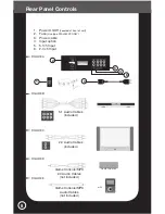
cables (included) to the “AuDIO OuT” channels on the
DVD player and the other end to the 2.0 channel inputs on the
Entertainment and Gaming Center.
5a. 5.1 Input Channels
FL = Front Left
FR = Front Right
SL = Side Left
SR = Side Right
C = Center
W = Subwoofer
2.0 Input Channels
L = Left
R = Right
6. Connect the video cables (not included)
from the component video outputs on
your DVD player, (consult DVD manual)
to the component video inputs on your TV
set (consult TV manual). Check that all of
your connections are secure
7. Plug in all of your audio/video equipment, you are now ready
to turn the system on. Carefully slide the Entertainment and
Gaming Center to the wall, (DO NOT LIFT) leaving a clearance
of approximately 6” (15cm) behind the systems. This spacing
is to allow for proper ventilation of all components.
8. The power (on/off) switch for the Entertainment and Gaming
Center is located at the middle front edge on the underside of
the main console.
Assembly Instructions
4
DVD
L
R
RCA to RCA
TV
FL
SL
SR
FR
C
W
FUSE
ON
OFF
GAME INPUT
MP3 INPUT
MALE END
FEMALE END
GAME CONSOLE
MP3
T2AL 250V
DVD
L
R
RCA to RCA
TV
FL
SL
SR
FR
C
W
FUSE
ON
OFF
GAME INPUT
MP3 INPUT
MALE END
FEMALE END
GAME CONSOLE
MP3
T2AL 250V
DVD
L
R
RCA to RCA
TV
FL
SL
SR
FR
C
W
ON
OFF
GAME INPUT
MP3 INPUT
MALE END
FEMALE END
GAME CONSOLE
MP3
T2AL 250V
DVD
L
R
RCA to RCA
TV
FL
SL
SR
FR
C
W
FUSE
ON
OFF
GAME INPUT
MP3 INPUT
MALE END
FEMALE END
GAME CONSOLE
MP3
T2AL 250V
DVD
L
R
RCA to RCA
TV
FL
SL
SR
FR
C
W
FUSE
ON
OFF
GAME INPUT
MP3 INPUT
MALE END
FEMALE END
GAME CONSOLE
MP3
T2AL 250V
DVD
L
R
RCA to RCA
TV
FL
SL
SR
FR
C
W
GAME INPUT
MP3 INPUT
MALE END
FEMALE END
GAME CONSOLE
MP3
T2AL 250V
DVD
L
R
RCA to RCA
TV
FL
SL
SR
FR
C
W
ON
OFF
GAME INPUT
MP3 INPUT
MALE END
FEMALE END
GAME CONSOLE
MP3
T2AL 250V
2.0 5.1


