background image

49


12.


SETTINGS - EVENTS 

12.1.1


I/O Events 

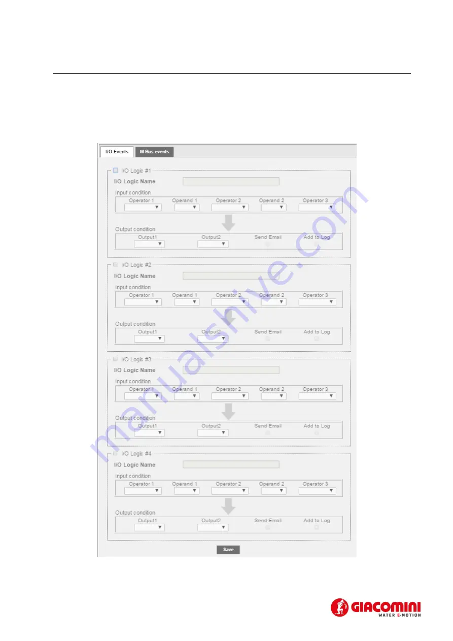
This section allows you to set up to four conditions to control the actuators. Ref. 5.1.9. With reference to 
that  described  in  Chapter  5.1.9,  the  device  is  equipped  with  three  digital  inputs, 

I1

I2

,  and 

I3

  and  two 

digital outputs 

O1

 and 

O2

. Figure 37 shows an example of programmable logic.  


Figure 37 – Logic 

Summary of Contents for GE552Y051

Page 1: ...GE552Y051 Datalogger for meters with M Bus protocol 20 Dev UserGuide Rev 1 3 This User Guide refers to versions of Firmware 4 06 xx Web 2 13 xx Hardware 2 0 ...

Page 2: ...ation 11 5 1 3 Serial connection to the LEVEL CONVERTER 11 5 1 4 Connection to a local PC via Ethernet LAN 12 5 1 5 Connection to a GPRS UMTS modem router 13 5 1 6 Connecting the digital inputs to voltage free contacts 14 5 1 7 Connecting the digital inputs to positive voltage contacts 14 5 1 8 Connecting the digital inputs to negative voltage contacts 15 5 1 9 Digital output connection 16 6 COMMI...

Page 3: ...ents 50 12 1 3 Condition set according to the maximum value acquired 51 12 1 4 Condition set according to the minimum value acquired 52 12 1 5 Condition set according to the value out of range 53 12 1 6 Condition set according to the M Bus status 54 13 SETTING GROUPS 56 13 1 1 Group creation 56 13 1 2 Group definition 57 14 DATA SAMPLING 59 14 1 1 Defining sampling frequency and RAW data M Bus cab...

Page 4: ... and csv 68 16 1 6 Planning 68 16 1 7 Repository 69 17 USER ACCOUNT 71 18 PLANT STATUS 72 18 1 1 Plant Status System Status System Status 72 18 1 2 Plant Status System Status Event Reports 73 18 1 3 Plant Status Wired Devices 74 18 1 4 Plant Status I O Devices 75 18 1 5 Plant Status Group 75 19 APPENDIX 76 19 1 1 ROUTER Configuration 76 ...

Page 5: ...protocol Please read carefully the following notes Place the system Firewall undercovered and isolate it from the corporate network For remote access to the machine we recommend the use of secure technologies such as Virtual Private Networks VPNs recognizing VPN in the most secure way to connect to the device The first section of this guide is dedicated to the description of the technical specific...

Page 6: ...il mounted inside an electrical panel The main technical specifications of the device are shown below Operating temperature range 20 55 C Storage temperature range 25 65 C Protection Rating IP20 EN60529 Fastening 35mm DIN bar EN60715 Dimensions 4 DIN modules 90x72x64 5 Power Supply 24Vdc 10 24Vac min 20Vac max 40Vac Power consumption Max 7 5W ...

Page 7: ...for logic control and remote control OLED display for local consultation and configuration 6 key membrane keyboard At the datalogger directly up to 20 M Bus meters can be connected with the help of SIN EQLC1 repeater it is possible to increase the number of up to 250 meters 3 1 2 GE552Y051 device An image of the GE552Y051 with its main functional parts is shown below Figure 1 View of the GE552Y051...

Page 8: ...han 20 M Bus nodes to manage with the same GE552Y051 one or more level converter in repeater mode can be used 4 1 2 M Bus system M Bus Meter Bus is a European standard EN 13757 2 phisical and link layer EN 13757 3 application layer for remote reading of water heat gas or electricity meters M Bus is also usable for other types of consumption meters The M Bus interface is designed to communicate on ...

Page 9: ...etween 00000000 and 99999999 By default the secondary address of the devices is the same as the manufacturer serial number Readings by secondary address while scanning the bus allow the acquisition of the meters that support the Wildcard logic the same that enables the selection of a group of devices based on the section of their serial number 4 1 4 Sizing the M Bus System Follow the instructions ...

Page 10: ...ation Condition Minimu m Typical Maximu m Measure ment unit Number of devices per segment n GE552Y051 0 20 Transmission rate T 382 300 2400 9600 Bd Bus voltage U IM 0 400mA 12 42 V Bus Voltage Master UM IM 0 400mA 24 40 42 V Bus Voltage slave US R 1 5 21 42 V Bus current IM V GE552Y051 0 90 mA DC Bus current IM K GE552Y051 130 500 160 mA Current slave IS R US 21 42V 0 75 1 2 1 2 mA Transmitted cur...

Page 11: ...erminals from the device pulling outwards Tighten the cables to the removed terminal complying with the right polarity Reinsert the terminal with the cables placing it in its correct position 5 1 2 Electrical installation Verify the following before commissioning the device Ensure that the electrical panel where the device is installed is powered off Verify the presence of power supply protection ...

Page 12: ... blinking in synch with every communication with the M Bus devices connected to it 5 1 4 Connection to a local PC via Ethernet LAN The device is equipped with two Ethernet ports ETH1 and ETH2 to connect it to a PC either connected to a LAN network or directly via an Ethernet cable Figure 5 LAN connection The default GE552Y051 network settings are IP address 192 168 1 110 Netmask 255 255 255 0 IP a...

Page 13: ...tion Static To change the IP address of the computer network adapter refer to the user manual of the Operating System of your PC In the event that the PC and the GE552Y051 are connected via an existing LAN company or domestic network make sure not to allocate the IP address of the GE552Y051 or of the PC For instructions on how to change the IP address of your PC refer to your current OS 5 1 5 Conn...

Page 14: ...to the Appendix Chapter 19 for in detail information on router settings 5 1 6 Connecting the digital inputs to voltage free contacts Follow the instructions below to connect the digital inputs to the device with voltage free contacts such as switches interface relays or anything else that does not require voltage Figure 7 Digital input connection Connect the digital input common 7 to the Vout term...

Page 15: ...digital inputs to negative voltage contacts Follow the instructions below to connect the digital inputs to the device with negative voltage in the event of closed contacts and voltage free contacts in the event of open contact Figure 9 Negative voltage digital input connection Connect the common pole positive of the contact to the common terminal 7 of the device Connect the negative pole of the co...

Page 16: ...tems Outputs O1 and O2 can be controlled both remotely and via web server Ref Chapter 11 1 10 For connection to electrical loads follow the model in Figure 10 and the maximum values for each relay shown below 5A 250Vac Resistive Load 5A 30Vdc Resistive Load 2A 250Vac Inductive Load cosfi 0 4 L R 7ms 2A 30Vdc Inductive Load cosfi 0 4 L R 7ms Figure 10 Digital output connection ...

Page 17: ...cking on OK on the SEARCH icon 3 Verify wired Meters REQUIRED Once the search is complete the list of meters is displayed together with the communication status OK or ERROR as shown in the figure Press OK in correspondence of a meter to access the latest reading performed 4 Access to Webserver RECOMMENDED After two scanning phases described above we recommend accessing the GE552Y051 s webserver to...

Page 18: ...se are shown in the heading of the reports generated by the datalogger See Chap 11 to set the plant database 7 Email settings RECOMMENDED To allow the datalogger to notify reports events or anomalies errors in a plant we recommend setting the Email section carefully See Chapter 11 1 8 for the email settings 8 Display Webserver password changes HIGHLY RECOMMENDED Before completing the commissioning...

Page 19: ...se upon entering the password in the main menus such as WIRED METERS WIRED METERS SEARCH and SETTINGS menus all you have to do is press the arrows or to change the language The available languages are English and Italian Refer to Chapter Errore L origine riferimento non è stata trovata for instructions to change the language via the Web ...

Page 20: ... the language between Italian and English in the GE552Y051 INFO WIRED METERS WIRED METERS SEARCH and SETTINGS menus 8 1 2 Display The GE552Y051 is equipped with a 96x128 pixel resolution OLED display 16 level greyscale which allows the consultation of the readings and basic settings of the GE552Y051 To minimise electricity consumption the display turns off automatically after 10 minutes of inactiv...

Page 21: ...he device and the current date and time As for the content of the single sections we have 1 1 o Serial Number Shows the serial number to be indicated in the event of technical support o Meter DB Ver Shows the version of the meter database installed in the datalogger 1 2 o LAN ETH status Indicates the connection status of Ethernet ports ETH1 and ETH2 In the event at least one of the two ports is co...

Page 22: ... reading 2 2 press OK in correspondence of a meter in the list to view the values of the last reading if any The first frame indicated in Figure 14 is common to all three meters as it is a summary of the main information pertaining to the meter such as the M bus status byte value meter reading value and the full serial number If the M Bus status byte is different from zero it indicates possible me...

Page 23: ... Description Shows the field description as defined in the M Bus protocol Field value and measurement unit Indicates the value and measurement unit of the field displayed with reference to the reading being viewed M bus Storage Number Indicates the Storage Number of the displayed field Refer to the meter manual guide for further information M bus Subunit Number Indicates the Subunit Number of the ...

Page 24: ... SEARCH Press OK in correspondence of the SEARCH WIRED icon to start scanning the bus and acquire the connected meters The search settings are those that have been previously saved as shown in Chapter 6 The default search settings are Transmission rate 2400bps Type of search Primary ID Secondary ID Primary ID scanning interval 1 250 The figure below shows a typical bus scan with the default settin...

Page 25: ...ast block press OK to save all the meters found otherwise press ESC if you do not want to save any of the meters found Refer to the WEB section Chapter 11 1 11 11 1 12 11 1 14 to change or complete the settings of the meters found in this section ...

Page 26: ... The default GE552Y051 network settings are IP address 192 168 1 110 Netmask 255 255 255 0 IP allocation Static In order for the computer to communicate with the GE552Y051 via Ethernet the IP address of the computer s network adapter must be set as follows IP address 192 168 1 XXX With XXX being a number ranging between 1 and 254 and different than 110 Netmask 255 255 255 0 IP allocation Static To...

Page 27: ...wser Figure 18 Login The credentials for the first access are Username admin Password admin Press the button to access Log In The Home Page appears as shown below Figure 19 Home Page The screen is divided into three sections In consultation page path User type connected selected language 1 1 2 3 ...

Page 28: ... devices o I O devices o Groups Settings o System o Network o Wired devices o Events o Groups Export Data o Create Report o Pianning o Repository User Account o Login o Esc Returns the sub menu with the entries for the main menu Section 2 3 2 ...

Page 29: ...DNS Wired Devices o Meter Setup o Search Setup Wireless Devices o Devices o Wireless Setup o Devices commissioning Events o I O Events o M Bus Events Events o Groups o Definition 11 1 1 SETTINGS SYSTEM Below the SETTINGS SYSTEM menu items are shown 11 1 2 Plant Database You can add only one plant for every GE552Y051 Figure 20 Plant data settings Enter the plant data ...

Page 30: ... synchronising them with your PC 2 System configuration LEVEL CONVERTERD Password allows changing the password to access the controls on the device display The default password is 000000 System Restart allows you to restart the GE552Y051 Reset to factory default allows you to initialise the device according to the default settings Selecting Reset to factory default will be reset the GE552Y051 conf...

Page 31: ...ESH THE WEB PAGE 2 Backup Restore Configuration System Configuration Backup select if you want to create a system backup Press Create Backup to complete the operation See Figure 23 Meter Configuration Backup select if you want to create a meter configuration backup Press Create Backup to complete the operation See Figure 23 Restore Configuration select it if you want to restore the configuration o...

Page 32: ...ss Enable DHCP select if you want to use the DHCP protocol IP Address sets the machine s static LAN address Gateway address sets the address of the LAN Gateway Network Mask sets the LAN subnet mask Primary DNS sets the primary DNS address Secondary DNS sets the secondary DNS address Pay particular attention to the insertion modification of LAN parameters Always refer to a home or corporate network...

Page 33: ...etwork settings The fields to fill out in this section are HTTP Portforward defines the external HTTP port if configured differently from 80 to ensure that emails are sent correctly See Figure 26 DHCP TimeOut enter a timeout beyond which the destination will be declared unreachable SNPDS Hostname enter if used the remote address of the SNPDS service CPU TCP Port not used Figure 26 Network infrastr...

Page 34: ...guration Press Test to verify whether the entered parameters are operating properly if not refer to Chapter 11 1 7 2 Alarm Email management Enable alarm email notification Enable email notification upon alarm present in plant and acquired by the GE552Y051 device The system will also manage an automatic signaling of alarm communication error if one or more devices in the field do not respond correc...

Page 35: ... to save the configuration 11 1 10 SETTINGS WIRED DEVICES This section allows you to configure search the meters in the plant 11 1 11 Search Setup To search the meters go to Meters Search Meter This section provides two types of search manual and automatic We recommend opting for the automatic search Use the manual search only in the event that one or more devices are not recognised by the automat...

Page 36: ... search 2 Manual search use this option only in the event that one or more devices are not recognised during the automatic search Use default settings if selected it automatically sets the baudrate to 2400 otherwise you can also select the baudrate for the search Baudrate Search set the non standard communication speed with which you want to query the devices that were not automatically recognised...

Page 37: ...s particular example the devices were searched by primary secondary address You can interrupt the search at any time by pressing Stop Figure 31 Searching devices At the end of the search you can select the meters found See Figure 32 Figure 32 Saving the meters At the end of the research we will have two types of devices ...

Page 38: ...ur 6 hours 12 hours 1 day 1 month ID Device indicates the serial number of the selected meter Manufacturer Code indicates the manufacturer s name in the event that the meter in the database is identified by the GE552Y051 Measured value indicates the type of value read by the meter Version HEX indicates the version of the meter Manufacturer indicates the manufacturer s name in the event that the me...

Page 39: ...39 11 1 13 Meters built into GE552Y051 DataBase Figure 33 Meter setup 2 1 3 4 ...

Page 40: ...range between 1 and 250 not modifiable Baudrate Indicates the speed with which the meter communicates with the GE552Y051 Check the meter manual to verify the communication speed Request by allows you to perform a reading by primary or secondary address ID device indicates the serial number of the selected meter not modifiable Manufacturer Code indicates the manufacturer s name in the event that th...

Page 41: ... daily delta o Min of Day generates data as the minimum value of the day o Max Of Day generates data as the maximum value of the day o Average generates data as the average of the day Show data select which data to include in the Homepage Main Field this is the main value which you want to view in the home page Save to save any changes 4 Meter alarm settings every meter has a series of errors that...

Page 42: ...puts or not when an event occurs Ref 5 1 9 o Output 1 when an alarm occurs you can enable an operation according to the device connected to Output 1 such as o Open commands to open o Close commands to close o Pulse generates a pulse o Output 2 when an event occurs you can enable an operation according to the device connected to Output 2 such as o Open commands to open o Close commands to close ...

Page 43: ...m email notification is active Event name shows the name of the event Data coming from the device according to the modifiable protocol standard Event type shows the type of event Data coming from the device according to the modifiable protocol standard Status shows the alarm status activated or deactivated Data coming from the device according to the modifiable protocol standard After making all t...

Page 44: ...44 11 1 14 Meter Setup Meters not built into GE552Y051 DataBase Figure 35 Meter setup The screen is divided as follows 1 Meter table 2 1 3 4 ...

Page 45: ...meter communicates with the GE552Y051 Check the meter manual to verify the communication speed Request by allows you to perform a reading by primary or secondary address ID device indicates the serial number of the selected meter not modifiable Manufacturer Code indicates the manufacturer s name in the event that the meter in the database is identified by the GE552Y051 not modifiable Measured valu...

Page 46: ...he end of the day and corresponding daily delta o Min of Day generates data as the minimum value of the day o Max Of Day generates data as the maximum value of the day o Average generates data as the average of the day Show data select which data to include in the Homepage Main Field this is the main value which you want to view in the home page Save to save any changes 4 Meter alarm settings in t...

Page 47: ... 1 when an alarm occurs you can enable an operation according to the device connected to Output 1 such as o Open commands to open o Close commands to close o Pulse generates a pulse o Output 2 when an event occurs you can enable an operation according to the device connected to Output 2 such as o Open commands to open o Close commands to close o Pulse generates a pulse o Add to Log stores the alar...

Page 48: ...ame shows the name of the event Data coming from the device according to the modifiable protocol standard Event type shows the type of event Data coming from the device according to the modifiable protocol standard Status shows the alarm status activated or deactivated Data coming from the device according to the modifiable protocol standard After making all the changes confirm them through the ap...

Page 49: ...et up to four conditions to control the actuators Ref 5 1 9 With reference to that described in Chapter 5 1 9 the device is equipped with three digital inputs I1 I2 and I3 and two digital outputs O1 and O2 Figure 37 shows an example of programmable logic Figure 37 Logic ...

Page 50: ...See Chapter 18 1 2 Press Save to save the settings 12 1 2 M bus events This section allows you to set the conditions with data coming from the meters in the plant to control outputs O1 and O2 Press the New Event button as shown in Figure 39 to generate a new event Figure 39 Creating a new event Select a meter from which you want to obtain data to set the event Figure 40 Selecting a meter Upon sele...

Page 51: ...e Figure 42 Completing the creation of an event The cells to be filled out are Event Name enter the name of the event being created Data Type select the type of meter data The data you can select are those that have already been set for every single meter For more information refer to Chapter 11 1 12 Alarm threshold Max select an alarm threshold The value can be both positive or negative Dead band...

Page 52: ...ess Save to save the configuration 12 1 4 Condition set according to the minimum value acquired Select Min Value Figure 44 Completing the creation of an event The cells to be filled out are Event Name enter the name of the event being created Data Type select the type of meter data The data you can select are those that have already been set for every single meter For more information refer to Cha...

Page 53: ...tion set according to the value out of range Select the Out of range item Figure 46 Completing the creation of an event The cells to be filled out are Event Name enter the name of the event being created Data Type select the type of meter data The data you can select are those that have already been set for every single meter For more information refer to Chapter 11 1 12 Lower threshold select the...

Page 54: ... Bus status Select the M Bus status notify item Figure 48 Completing the creation of an event The cells to be filled out are Event Name enter the name of the event being created Data Type select the type of meter data The data you can select are those that have already been set for every single meter For more information refer to Chapter 11 1 12 Event closure notification sends an email notificati...

Page 55: ...o Close commands to close o Pulse generates a pulse Add to Log stores the alarm in the meter s log Send Email sends an email notification in the event of an alarm Ref Chapter 5 1 4 8 1 4 Save Press Save to save the configuration ...

Page 56: ...n in divided into Groups section dedicated for the groups creation Definition section dedicated for the group definition Definition is mean the inclusion inside the groups of the devices previously configured in the GE552Y051 Figure 49 Groups management 13 1 1 Group creation To create a group just select NEW associate a name and press OK Figure 50 Group creation Following the creation of the group...

Page 57: ...p Ref 13 it will be possible to define the components of the group The window is divided into two separate boxes a Left boxe displays all prevously configured devices in the GE552Y051 b Right boxe shows all the devices configured nell GE552Y051 and already forming part of a selected group A single device can be placed in either the right boxe or the left boxe through the directional arrows placed ...

Page 58: ...up of interest in the Group ID box 2 Select the device you want to include in the group 3 Press the left arrow to include it At the end of the operations always press the APPLY button to set the changes Refer to Chap 16 1 5 for the use of the Group ...

Page 59: ...efined as RAW samples RAW samples will always refer to the consulted day and you can store up to 96 samples for every day of the year for 250 devices The samples of the previous year will be cyclically deleted from the GE552Y051 mass memory Ref Chapter 16 Pay special attention to the documentation of the devices before configuring the GE552Y051 sampling frequency If the sampling value is too high ...

Page 60: ...nging any type of data involves regenerating all the data in the logfile of the data already generated in the GE552Y051 The summary data are None no data displayed Consumption generates data as the maximum value at the end of the day and corresponding delta Minimum generates data as the minimum value of the day Maximum generates data as the maximum value of the day Average generates data as the av...

Page 61: ... Summary data related to Maximum provide the maximum value logged during the day Figure 56 Summary data Maximum 15 1 4 Summary Data Minimum Summary data related to Minimum provide the minimum value logged during the day Sampled Value Sampled Value Sampled Value Sampled Value Time axis Time axis Time axis Time axis Sampled Value Sampled Value Sampled Value Sampled Value Time axis Time axis Time axi...

Page 62: ... to Average provide the averaged value logged during the day Figure 58 Summary data Average Sampled Value Sampled Value Sampled Value Sampled Value Time axis Time axis Time axis Time axis Sampled Value Sampled Value Sampled Value Sampled Value Time axis Time axis Time axis Time axis ...

Page 63: ...ports Meters Groups Planning Repository Every item will be described separately 16 1 1 Create Reports Meters The pages to Create Reports Meter are described below Figure 59 Creating a report Select one or more devices from the list For this option all you have to do is select the box on the top left of the table See Figure 60 Figure 60 Selecting the devices The Create report menu is divided as fol...

Page 64: ...hich to start the export o To select the day on which to end the export o CSV format to save in a CSV file o XLS format to save in a XLS file o Press Create Report to download the data o The file name will be created automatically and it will refer to the selected dates o Mouse over the newly created file and left click on it to open it b Export RAW data See Chapter 14 o Select the day select the ...

Page 65: ...ata o The file name will be created automatically and it will refer to the selected dates o Mouse over the newly created file and left click on it to open it If you use an XLS format press YES to view it correctly Figure 61 Excel 16 1 2 Example of RAW data in xls format Figure 62 Exporting RAW data in xls format ...

Page 66: ...Exporting Summary data in XLS and CSV format Note the extracted data from the system provide Use of the point for the thousands Use of the comma for the tens 16 1 4 Create Reports Groups The pages to Create Reports Group are described below Figure 64 Creating a report ...

Page 67: ...ted with the group 4 Data to be exported you can choose between two types of export o From select the day from which to start the export o To select the day on which to end the export o CSV format to save in a CSV file o XLS format to save in a XLS file o Press Create Report to download the data o The file name will be created automatically and it will refer to the selected dates o Mouse over the ...

Page 68: ... Planning This section allows you to 1 choose the period when to create the reports that will be viewed in the future in the Repository section 2 activate the File Transfer Protocol FTP to transfer the data to an external server Figure 68 Planning Planning refers to every single device and the document that will be created can always be viewed in the Report Archive section See Chapter 16 1 7 To se...

Page 69: ...od Annual enables annual planning at 08 15 AM of the last day of the year XLS report format select if you wish to export the report to an XLS file CSV report format select if you wish to export the report to an CSV file 2 FTP file transfer File Transfer Protocol Figure 70 FTP Activation Enable FTP push select if you want to enable the FTP service FTP server address enter the address of the FTP ser...

Page 70: ...ading the file select it in the lower section of the browser page A window prompting you to confirm whether you want to open the file will appear automatically Press YES to open the file Figure 72 Excel press the button to delete the record ...

Page 71: ...tained in the GE552Y051 The admin account allows you to view and change all the data contained in the GE552Y051 The default access data for the User are Username user Password user Re type password user Press Save to save the configuration The default access data for the Admin user are Username admin Password admin Re type password admin Press Save to save the configuration Figure 73 Account confi...

Page 72: ...Devices screen is divided into Model shows the GE552Y051 model Controlled Devices shows the type of devices controlled by GE552Y051 System clock shows the current date and time of the GE552Y051 GE552Y051 Firmware Version shows the firmware version Web Interface Version shows the web interface version Serial number shows the serial number of the machine Internet connection shows the Internet connec...

Page 73: ...during the year selected from the drop down menu Update updates the display of events according to the selected items described below All shows if selected all the events Email shows hides if selected the events with email notification I O shows hides if selected the input output events M Bus shows hides if selected the M Bus events FTP Report shows hides if selected the FTP events ...

Page 74: ...its serial number model device name description and main value Ref Chapter 11 1 12 Select a line corresponding to a meter and a window with all the relative information will be displayed as shown in Figura 76 If highlighted in Red it means there is an Error Checked the Error entry it displays only the meters that are in a state of communication error ...

Page 75: ...he configuration Rif Chap 12 18 1 5 Plant Status Group Figure 78 Groups Shows all groups previously configured in the GE552Y051 For each group is given the name and the underlying devices to the group Ref Chap 16 1 4 Checked the Error entry displays only the group that contains meters that are in a state of communication error ...

Page 76: ...nformation to ensure router operation Check the connection status to ensure the presence of a signal From the menu at the top press Status followed by Network Information A window will appear as shown in Figure Figure 1 Network Information For an acceptable Internet connection which allows internet browsing you need to have at least two green bars on the Signal Strength line If not connect the sec...

Page 77: ...od and any username and password Remember for every operation to select the Save button located at the bottom right of each configuration page The screen below shows the LAN submenu which is also part of the Network section Figure Figure 3 Common Configuration It possible to change the IP address of the router and eventually enable the DHCP service by inserting the range of active ports in this ca...

Page 78: ...lect the type of key generator to protection and enter a password Click Save to save the settings See Figure Figure 5 Security To use Port Forwarding rules press Network from the main menu and then Firewall From the submenu that will be displayed you can access the Port Forwarding section and set its rules Figure Figure 6 Port Forwarding ...

Page 79: ...ic LAN IP address By default the rules in the router are Router external port 80 Equobox external port 8080 FTP Sending external port 21 FTP Command external port 20 Press Firewall from the menu at the top and then Traffic Rules to set security functions such as addresses to be filtered set HTTP addresses or asymmetric cryptographic protocols to manage the transfer of confidential information Figu...

Page 80: ...n in Figure Enable Ping Reboot flag Reboot router if no echo received flag Interval between pings 15 minuts Ping timeoute sec 10 seconds Packet Size 54 byte Retry count 5 Server to ping 208 67 222 222 Figure 9 Ping Reboot To change the system password access the System section from the main menu and click on the Administration submenu Figure You can upgrade the Firmware or upload a previous config...

Page 81: ...81 Figure 10 Administration properties Figure 11 Backup and Firmware To set up the Dynamic DNS service go to menù Services Dynamic DNS Figure 12 Figure 12 Dinamic DNS service activation ...

Page 82: ...ssword for access to desired service IP renew interval min enter a time interval for the renewal of IP If not specifically requested leave the default value Force IP renew min enter a time interval to force the renewal of the IP If not specifically requested leave the default value Figure 13 Access parameter configuration for Dinamic DNS To obtain the data for the correct filling of the fields ref...

Page 83: ...DEEE L appareil ne doit pas être jeté avec les ordures ménagères car il est fait de différents matériaux pouvant être recyclés dans des centres appropriés Renseignez vous auprès de l autorité locale concernant l emplacement des plates formes écologiques appropriées pour recevoir le produit pour sa destruction et son recyclage correct ultérieur Il convient également de rappeler que en cas d achat d...

Reviews: