background image

6

Giacomini S.p.A.

Via per Alzo 39, 28017 San Maurizio d’Opaglio (NO) Italia

 consulenza.prodotti@giacomini.com

 +39 0322 923372 - giacomini.com

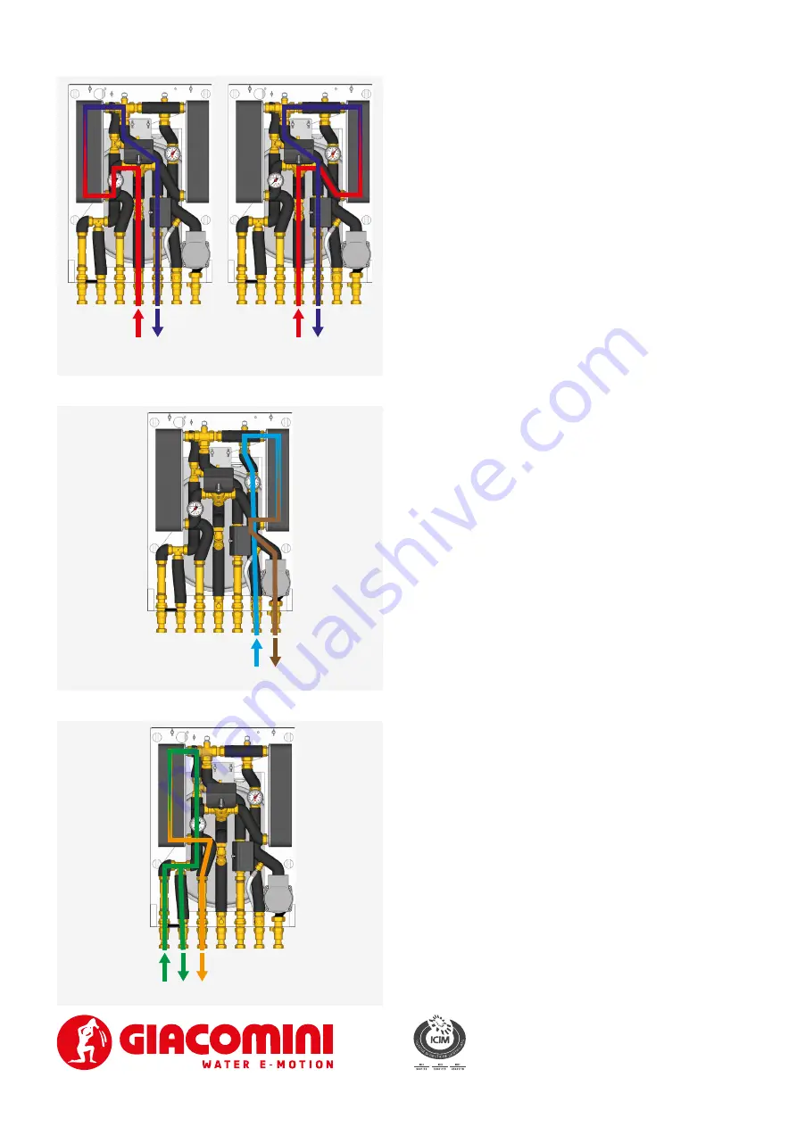
Secondary circuit: DHW

Cold  water  inlet  (A),  cold  water  outlet  (B)  and  hot  water 
outlet (C).
The DHW circuit consists of a flow switch, a check valve on 
the DCW inlet and two brass spacers for the introduction of 

the water meters.

A B

C

Primary circuit

Primary inlet (D) and outlet (E). The primary circuit consists 
of a filter, a three-way motorized priority valve, an manual 
air  vent  valve,  a  heat  exchanger,  a  pressure  gauge  and  a 
two-way motorized zone valve.
Energy  Saving  function:  the  two-way  modulating  valve 

controlled by the electronic management of the HIU, 

restricts the flow demand from the primary to the minimum 
necessary to obtain the preset Set-Point temperature.
The priority valve diverts the flow in the heat exchanger (if 
there is a request of DHW: DHW flow switch enabled) or in 

the heating system.
The thermal energy meter can be installed in place of the 

brass  spacer,  fitting  its  temperature  probe  in  the  relative 
housing (Components - Ref. 1).

D

E

D

E

Primary DHW circuit

Primary heating circuit

Secondary circuit: heating

Delivery (G) and return (F). The heating circuit consists of a 
heat exchanger, an manual air vent valve, a pressure gauge, 
a  minimum  pressure  switch,  a  safety  valve,  an  expansion 
vessel and a high-efficiency circulator (ErP 2009/125/EC).

F

G

Summary of Contents for GE556-6 Series

Page 1: ...th centralised heat production e g district heating The configuration with two heat exchangers in parallel provides the following advantages parallel and non intermittent handling of the domestic hot...

Page 2: ...l configuration heating and DHW production with priority for DHW production Flow switch for priority of DHW production Expansion vessel safety valve and high efficiency circulator 15 7 comply with ErP...

Page 3: ...DUCTION 10 Flow switch 11 Brass spacer for water meters 12 Check valve HEATING 13 Minimum pressure switch 14 Circulator 15 Pressure gauge 6 bar 16 Heat exchanger for heating function 17 Manual air ven...

Page 4: ...35 template with shut off valves and 22 mm system connections GE551Y136 template with shut off valves and 3 4 M system connections GE551Y136 Template with 7 valves connections from below GE551Y135 Tem...

Page 5: ...Safety valve Expansion vessel Manual air vent valve Circulator Heat exchanger Pressure gauge P P Minimum pressure switch Temperature probe F Flow switch Check valve E E Brass spacer for thermal energy...

Page 6: ...ing function the two way modulating valve controlled by the electronic management of the HIU restricts the flow demand from the primary to the minimum necessary to obtain the preset Set Point temperat...

Page 7: ...sh Turn the knob to select the desired value DHW Set point press key until the icon and the DHW set point value start to flash Turn the knob to select the desired value Kd this setting is only availab...

Page 8: ...WINTER and HEAT ONLY operating modes The function is enabled disabled by setting the t13 parameter via remote control Once activated it forces a request for operation in heating mode at a setpoint es...

Page 9: ...nting function is initiated and lasts 10 minutes The top and bottom LED rows flash in turn at 1 second intervals To cancel press and hold the operating button for 3 seconds After venting the LED displ...

Page 10: ...16 SAFETY THERMOSTAT K373 K373I REMOTE CONTROL K480Y002 MULTIZONE ADDITIONAL CONTROL EXTERNAL TEMPERATURE PROBE K365P 230 Vac WARNING Work on electrical components must be carried out by qualified pe...

Page 11: ...ry WARNING Flush all pipes before installing the HIU on the template WARNING Unused connections and ball valves must be closed with a cap WARNING Upon installation also include a filling circuit for t...

Page 12: ...2 80 150 30 75 170 30 70 175 30 65 210 31 60 260 32 LOW TEMPERATURE HEATING t 45 40 C PRIMARY CIRCUIT WORKING CONDITIONS CIRCULATOR SPEED FLOW RATE l h POWER kW T INLET C FLOW RATE l h T OUTLET C MAX...

Page 13: ...TION t 35 30 C PRIMARY CIRCUIT WORKING CONDITIONS FLOW RATE l min FLOW RATE l h POWER kW T INLET C FLOW RATE l h T OUTLET C 12 720 33 80 470 18 5 75 540 21 5 70 610 22 65 700 23 15 900 42 80 610 20 5...

Page 14: ...delivery C T primary return C 12 l min 15 l min 17 l min 20 l min Reduced flow rates requests to the primary in heating operation 65 70 75 80 T primary delivery C 600 700 800 900 1000 1100 1200 1300...

Page 15: ...250 42 65 310 42 60 400 42 HIGH TEMPERATURE HEATING t 60 45 C PRIMARY CIRCUIT WORKING CONDITIONS CIRCULATOR SPEED FLOW RATE l h POWER kW T INLET C FLOW RATE l h T OUTLET C MAX 1400 24 5 80 750 48 75...

Page 16: ...OW RATE l h POWER kW T INLET C FLOW RATE l h T OUTLET C 12 720 33 80 465 17 5 75 510 18 5 70 580 20 65 670 22 15 900 42 80 595 19 5 75 660 20 5 70 750 22 65 880 24 17 1020 47 5 80 700 21 75 770 22 70...

Page 17: ...C T primary return C 24 l min 12 l min 15 l min 17 l min 20 l min 22 l min Reduced flow rates requests to the primary in heating operation High temperature 65 70 75 80 T primary delivery C 600 700 80...

Page 18: ...water outlet D Primary inlet E Primary outlet F Heating return G Heating delivery X Fairleads Y Hole for safety valve drain Dimensions in mm HIU GE551Y135 TEMPLATE 460 55 60 325 845 60 60 60 60 60 45...

Page 19: ...ni com 39 0322 923372 giacomini com WRAS certification REF IN COMPONENTS PARAGRAPH COMPONENT CERTIFICATE NUMBER Gaskets 1509514 10 Flow switch 1605300 5 16 Heat exchanger 1909083 Reference Standards U...

Page 20: ...ates formes cologiques appropri es pour recevoir le produit pour sa destruction et son recyclage correct ult rieur Il convient galement de rappeler que en cas d achat d un appareil quivalent le distri...

Reviews: