KDVRAY500 MANUAL
Pag. 3 of 24
Components
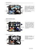
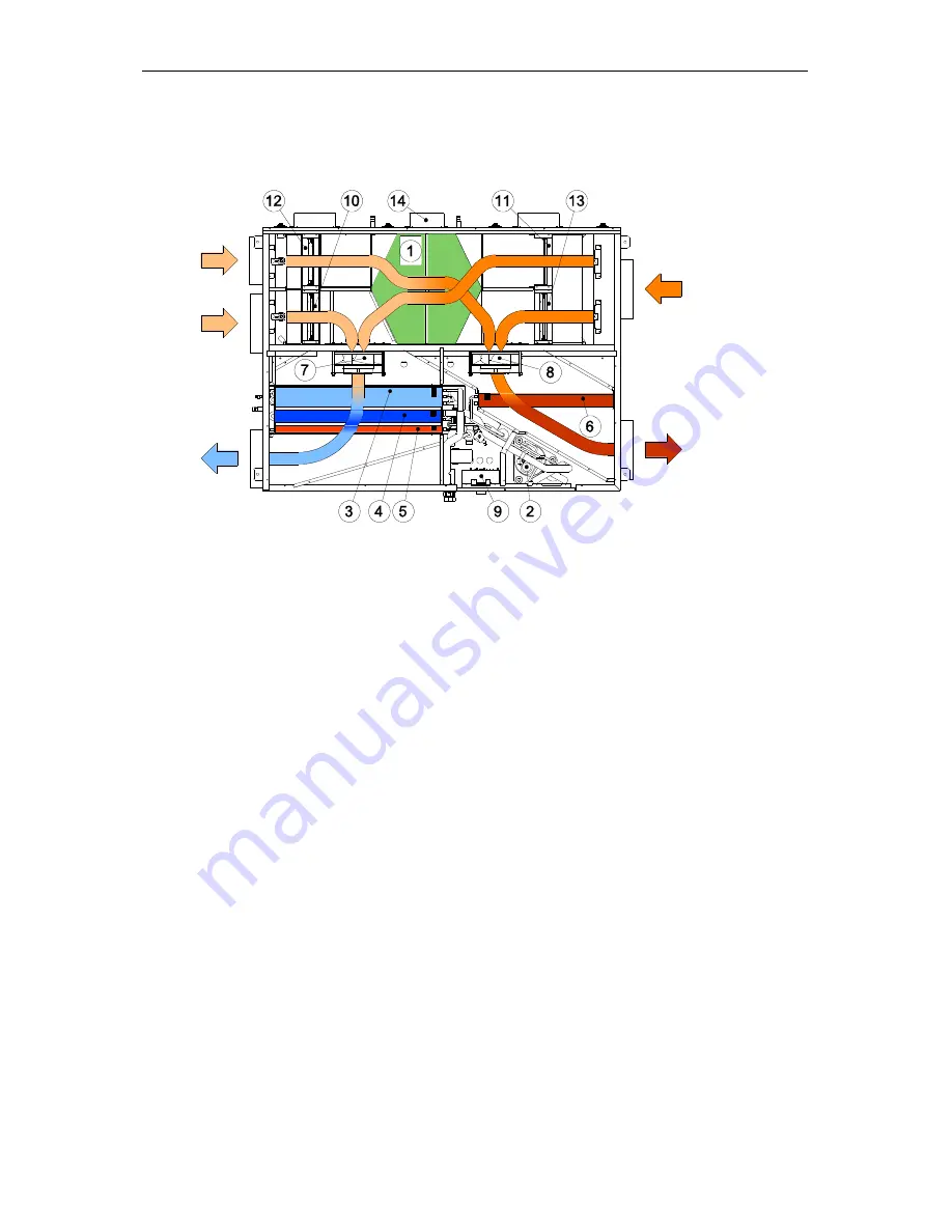
The following figure shows the machine from above, the main components and the air flows
inside it.
The air flow rates treated by the machine can be set from the control panel. The fans
automatically move to the speed necessary to overcome the pressure drops in the ducts.
There can be two air flows in the machine: that of renewal with heat recovery, through the
counter-flow air / air recuperator (1), and that of recirculation of the ambient air.
The renewal and recirculation flows can be combined or not, depending on the flow rates and
the type of treatment to be carried out on the injected air.
There is also a duct, controlled by a motorized shutter, which allows the intake of external air
without passing through the recuperator. It is thus possible to exploit, if present, the free
contributions of outdoor air cooling. The bypass is activated automatically when there is the
appropriate consent and the outside temperature is within the set limits
1 - Heat recovery exchanger
2 - Compressor
3 - Water coil
4 - Evaporator coil
5 - Condensing coil
6 - Condensing coil for external heat transfer
7 - Inflow fan
8 - Discharge fan
9 – In key
10 - Ambient air recirculation damper
11 - Fresh air intake damper
12 - Stale air intake damper
13 - Supplementary air intake damper
14 – Recuperator bypass damper
OUTDOOR
INDOOR


