background image

Installation instructions

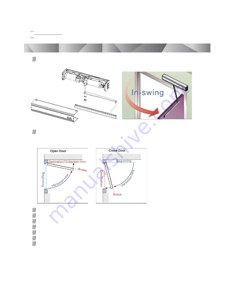
Opening, Closing action time and Maintain time illustration. AD425S will be automatically counted the 

round trip distance and can be adjusted the opening, closing and break time.

Figure 3

Figure 4

Opening angle: 90 degree. 

Beginning

Destination

Brake for the possible distance required to open the door.

VM Action time is the opening and closing time.

TC Maintain time is main-open time.

Prepare the installation

To mount the AD425S depends on the direction way of the doors, out-swing, in-swing, right-hand and 

left-hand doors by adjusting the F/R switch and the direction of the Operating Arm.

For the safety reason, AD425S must be installed indoor.

Automatic Door Operator 

Manual

8

Refer to Figure 3 for in-swing door (right-hand open)

Summary of Contents for AD-425S

Page 1: ...AD425S Instruction Manual Automatic Door Operator...

Page 2: ...sk exits of being crushed cut or gagged or where there are any other risks generated by the motorized door or gate Apply hazard areas notices required by applicable regulations Each installation must...

Page 3: ...cess is made to operate at the maximum permissible weight Service class product operation times and the number of consecutive cycles have been statistically analyzed to determine under average operati...

Page 4: ...ower to Open in case of emergencies or power interruptions 3 Automatic Door Operator Manual 17 Control Board Guide Input Output Contact Description Remark Power Switch Make sure the power input is app...

Page 5: ...sing status Jumper 1 3 is N O contact remain at opening status AD425S Operating Arms turns counter clockwise See P 9 Figure 5 8 DIP3 switch 2 when the external pressure force either WIND or MAN MADE F...

Page 6: ...or Motor power status indicator See P 3 N C N C is a normally closed contact and it is for fail safe Power to Lock Electric Locks N O N O is a normally open contact and it is for fail secure Power to...

Page 7: ...d status on DIP3 and adjust to high torque output Safety Device Do not push pull the door with excessive force during proper operation Excessive force will lead to auto shut off by control board and r...

Page 8: ...y 2400 RPM Battery charge 12V 0 15A Normal 0 3A Peak Dimensions Operator 526 L x 100 W x 96 D mm Arm 400 mm Door Dimensions cycle time See Figure 1 Door width 75 120 cm Door weight 50 100 kg Door Widt...

Page 9: ...the possible distance required to open the door VM Action time is the opening and closing time TC Maintain time is main open time Prepare the installation To mount the AD425S depends on the direction...

Page 10: ...n swing door F R switch set 1 Operating Arm mounts to left side Figure 8 For left hand in swing door F R switch set ON Operating Arm mounts to right side For Figure 5 7 Operating Arm mounts to left si...

Page 11: ...Install AD425S on an in swing door make sure that the distance between Square Couplings and hinge is not more than 74mm the space between header and the bottom of AD425S must be 23mm and the space bet...

Page 12: ...ng door Right Hand Open AD425S Template Installation Instruction Figure 19 In swing door Right Hand Open Figure 18 Out swing door Left Hand Open Figure 20 In swing door Left Hand Open 11 Automatic Doo...

Page 13: ...figure presented for an out swing door Right Hand Open more details shown in P 11 Figure 17 Step 2 Mark for pilot holes Use the center pointer Step 3 Mark six pilot holes one cable hole and center li...

Page 14: ...steps on other Blind Nuts Do not over tighten the Blind Nut Blind Nuts Installation illustration Step 8 Blind Nuts installation completed Step 9 Place the sliding rail template to the right position o...

Page 15: ...ntly fixed in the hole Repeat these steps on other Blind Nuts Do not over tighten the Blind Nut Step 13 Blind Nuts installation completed Step 14 Insert two mounting screws Step 15 This is the positio...

Page 16: ...uplings Step 20 Step 21 Slide the Operating Arm to Sliding Rail Step 22 Step 23 Slide in the Sliding Rail Cover Fix the Sliding Rail on the door leaf 3 pieces Insert screws M6 x 16mm gear type washer...

Page 17: ...microwave sensor reader and other accessories can be used with the AD 425S operator See the Control Board guide above on P 3 to wire these application Step 27 After the initial installation please co...

Page 18: ...eplace battery Battery is located on the back of Control Board Remove the Fixing Plug and old battery replace the new battery then tighten the Fixing Plug Trouble shooting Problem Possible Cause Solut...

Page 19: ...preset destination Problem Possible Cause Solution Make sure all motor terminals are connected properly Jump 1 8 is in HOLD mode Motor has no power LED motor light not on Transformer damage Contact yo...

Page 20: ...Manual The AD425S stops operating automatically when the door closing is interrupted for three times Make sure the door swing freely without any obstruction The door automatically stops before reachin...

Page 21: ...ng Do not allow children to play or stay within the field of action of the motorized door or gate Keep remote control or any other control devices out of the reach of children in order to avoid an une...

Page 22: ...Copyright A ll Rights Reserved P MU AD425S Ver D Publish 2010 01 01 AD425S Instruction Manual Automatic Door Operator...

Reviews: