2-2
1. Make sure the gap between the door top rail and the
frame header is within 2 mm.
2. Test the door operator on a single swing door to see
if it works. Check double swing doors to see if the
central lines on the door frame and door leaf align.
3. Mark the central lines on the door and frame where
the magnet assembly and armature assembly will be
installed.
4. Attach the templates to the door and frame.
5. Cut and drill holes where the templates indicate.
Connect the wires. Install the magnet assembly and
armature assembly towards the leading edge of the
door.
6. Connect to the power and check the unit.
A. For proper operation, the armature assembly must
be close and parallel to the magnet assembly, without
interfering with opening and closing of the door. Keep
a distance of 2 mm between the armature assembly
and the magnet assembly.
B. If the lock bolt attracts the armature assembly
when the door is not in position, please adjust the
door operator and floor hinges.
C. If there is no output from the bond sensor, please
remove secondary diode installed across the magnet
assembly. Also adjust the surfaces of the magnet and
the armature assembly.
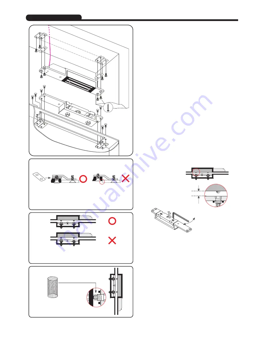
Mortise Installation
For Vertical Installation
Change the spring which is provided
in the screw pack.
Use tapping
Screws for
wooden door
Lea
ding e
dge
of d
oor
Flat Lugs is used when the door frame is deep, and to prevent
the Electromagnetic Lock or the Armature Plate caved in, add
flat lugs to raise the plane (level) of the Electromagnetic Lock
face or the Armature Plate face to the door frame surface.
Make sure the gap between the Shear Lock and the
Armature Plate are the same while adjusting the gap.
Proper operation cannot be expected with
more than 2 mm gap between the armature
and the magnet. Use the key wrench
provided to adjust the armature vertical
adjustment screws.
ke
y w
ren
ch
T h e G a p b e t w e e n t h e
m a g n e t a n d A r m a t u r e
plate is 2 mm
Copyright
Gianni Industries, Inc. All Rights Reserved.
P-MU-GS705N-30 Ver. E Publish:2011.12.16
©


