3
unit assembly & set-up (cont.)
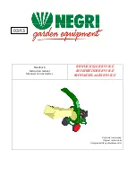
AXLE ASSEMBLY (CHW UNITS ONLY)
Safety Note: Assistance is required when installing axle. If access to lifting equipment
is possible, it is highly recommended.
•
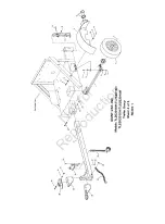
Drop one 1/2-13 x 1-1/4” bolt, fitted with one
1/2” flat washer, down through the two
outermost axle mounting holes located in each
of the two channels that run lengthwise under
the engine base (two bolts each side, four bolts
total).
•
Slide axle up onto bolts, making sure axle hubs
are offset toward rear of unit as shown.
•
Secure assembly with four 1/2” flat washers,
1/2” split lock washers, and 1/2-13 hex end lock
nuts.
•
Install tires onto axle hubs with lug nuts.
•
Slide Support Leg up through leg channel,
hollow of leg facing out to accommodate fender
bolt, and secure in uppermost position with
clevis pin and bridge pin.
Use outermost holes
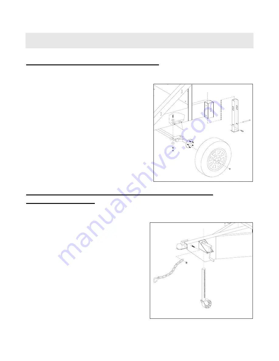
SUPPORT JACK AND SAFETY CHAIN INSTALLATION
(CHW UNITS ONLY)
Safety Note: Assistance is required when installing support jack. If access to lifting
equipment is possible, it is highly recommended.
•
Remove jack from upside-down shipping
position. Lifting draw bar, insert jack into crank
assembly, making sure teeth of jack point out
as shown. Crank jack up into crank assembly
until unit sits level with ground, then drop
support leg (installed in previous assembly
step), and lock in lowermost position possible.
This will prevent possible unit rollover while
installing discharge assembly.
•
Secure one Safety Chain onto each of the two
studs on either side of the draw bar front, with
one 1/2-13 reverse lock nut. Tighten snugly
while allowing free movement of chain link.
Note: fenders not
shown, to simplify
assembly diagram.
You may want to
attach fenders after
installing axle.
Not
for
Reproduction


