3
unit assembly & set-up (cont.)
•
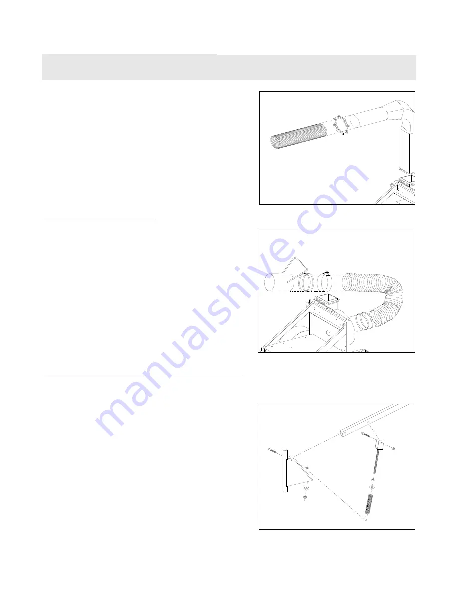
Slip one end of metal discharge hose (3:6)
onto barrel of discharge stack.
•
Secure hose in place with squeeze ring (3:7),
tightening all bolts securely enough to dimple
hose against barrel of stack and thereby
prevent slippage of hose on stack assembly.
INTAKE ASSEMBLY
•
Slip two hose clamps (2:9) onto one end of
intake hose (2:8), then slip end of hose onto
intake flange barrel (2:5), located in front of
impeller housing. Tighten clamps securely.
•
Slip Hose support band (2:10) about halfway
up the length of the hose, with eye clip
facing up.
•
Slip two hose clamps onto free end of intake
hose, followed by Intake Nozzle (2:11) with
handle pointed upwards and toward hose.
Tighten clamps securely.
HOSE SUPPORT BOOM ASSEMBLY
•
Attach yoke end of Threaded spring guide
(5:5) to second thru hole of horizontal boom
member (5:2) with one 1/2-13 x 3” hex bolt
(5:3), securing with 1/2-13 lock nut (5:4).
Do not over tighten lock nut. Note: Be sure
spring guide and chain eye at end of boom
are both toward bottom of boom member.
•
Attach horizontal boom member to vertical
boom member (5:1) with one 1/2-13 x 3”
hex bolt, securing with 1/2-13 lock nut. Do
not over tighten lock nut. Be sure spring
guide is toward base of vertical boom
member.
•
Remove 3/4” hex nut and flat washer (5:6-7)
from bottom of threaded spring guide. Slip
thread down through hole in base of vertical
boom member, securing with same hardware
as previously removed.
Manual No. 3100022
Not
for
Reproduction


