background image

12

7)  When reassembling: The inlet valve seat (51C) is 1mm 

smaller in diameter than the discharge valve seat (52C). 

Inlet valve seats are marked “S” and always have to be 

installed first. Discharge valve seats are marked “P” and 

are always to be installed on top of inlet valve. Plugs (58) 

are to be tensioned down evenly with screws (58C) and in 

crosswise pattern at 155 ft.-lbs. (210 Nm).

GP7122 REPAIR INSTRUCTIONS

11)  By  gripping  hex  flats, 

separate  plunger  (36) 

from crosshead (25) by 

means of two open-end 

wrenches (size 22mm 

and 27mm).

8)  Loosen nuts (49A) 

with a 24mm socket 

wrench.

9)  With a rubber mallet tap 

the back of the valve 

casing (50) and pull the 

valve casing off the stud 

bolt (49).

10) Remove  cover  plate 

(30)  with  a  10mm 

socket wrench.

Valve Seat identification markings

TO CHECK SEALS

13) Pull seal sleeves (38) 

and plungers (36) out 

of their fittings in the 

crankcase (1) using 

ring groove as a guide.  

Remove plunger from 

seal sleeve.

12)   Remove  tension 

spring  (40)  from  seal 

retainer (38).

CAUTION: 

 Don’t loosen the three plungers (36) before the valve casing has been 

removed otherwise the plunger (36) could hit against the spacer pipe (51F) 

when the pump is being turned.

Summary of Contents for GP7122

Page 1: ...7 Exploded View page 8 Parts List page 9 Kits page 10 Torque Specifications page 10 Repair Instructions pages 11 14 Dimensions page 15 Warranty Information back page Triplex Ceramic Plunger Pump Operating Instructions Repair and Service Manual Model GP7122 Updated 03 22 ...

Page 2: ... affect safety are identified by the following symbol see DIN 4844 W9 or where electrical safety is involved with see DIN 4844 W8 Safety measures which can cause damage to the machine if not adhered to are marked Important It is imperative that signs affixed to the machine e g arrow indicating the direction of rotation symbols indicating fluid connections be observed and kept legible 2 2 Qualifica...

Page 3: ...y air or air water mixture Cavitation and or compression of gases lead to uncontrollable pressure kicks which can ruin pump and unit parts and also be dangerous to the operator or anyone standing nearby Before pumping other liquids especially inflammable explosive and toxic media the pump manufacturer must under all circumstances be consulted with regard to the resistance of the pump material It i...

Page 4: ...rd the pump against pipeline tensions The diamater of the suction line must be at least one size bigger than the suction inlet port Important If there is a danger of frost the water in the pump and in the pump fittings particularly the unloader valve must be emptied The second discharge port can also be used and the pump run dry for 1 2 minutes for this purpose Important The pump is not to be conn...

Page 5: ...upture of the hose The M10 thread 18 deep on the valve body can be used for this Hydraulic System Set Up If a suitable safety has not been fitted to the pump head one must be installed immediately after the first length of flexible discharge line There are to be no shut off valves between the pump and safety valve An air vent should be built into the discharge line as near as possible to the pump ...

Page 6: ...check put the oil dipstick in the bore situated beside the eye bolt First oil change should be made after 50 hours of operation thereafter oil must be changed every 1000 operating hours or after 1 year if used less Caution When operating in damp places or with high temperature fluctuations Oil must be changed immediately should condensate frothy oil occur in the gear box Open all regulator valves ...

Page 7: ...e power outputs must be approximately twice the pump power requirements shown above We recommend a 1 15 service factor be speci fied when selecting an electric motor as the power source To compute specific pump horsepower require ments use the following formula GPM X PSI Consult the factory for special requirements that must be met if the pump is to operate beyond one or more of the limits specifi...

Page 8: ...8 Exploded View GP7122 ...

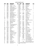
Page 9: ...522 Seal Case 3 39A 05523 O Ring 6 40 07338 Tension Spring 3 41 06753 Support Disc 3 42 06754 Spiral Ring Packing 6 43 06755 Support Ring 6 ITEM PART DESCRIPTION QTY 44 06756 Guide Ring 3 45 06757 Pressure Ring 3 46 13390 Seal Ring 3 47 06758 Spacer Disc 3 48 05524 Circlip 3 49 13159 Stud Bolt 8 49A 13160 Hexagon Nut 8 50 06759 NPT Valve Casing Assembly 51B F 1 50C 03397 Connection Nipple 1 2 FNPT...

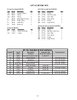
Page 10: ...g 6 42 06754 Spiral Ring Packing 6 43 06755 Support Ring 6 44 06756 Guide Ring 3 46 13390 Seal Ring 3 Oil Seal Kit 09221 Item Part Description Qty 32 07624 Radial Shaft Seal 3 33A 07627 O Ring 3 GP7122 TORQUE SPECIFICATIONS Position Item Description Lubricaion Info Torque Amount 1 07600 Crankcase Molycote Cu Paste 5 05798 Seal for Crankcase Cover Loctite 5910 10 22706 Hexagon Screw 33 ft lbs 45 Nm...

Page 11: ...t of valve casing 50 by tightening screws 58C against valve casing with two screws 4 Take out valve assemblies 52 51 using either tool part 07662 or an M16 stud bolt 3 Remove the compression spring 57 O Ring 58A and support ring 58B 58B 58A 57 5 Valve seats 51C and 52C are pressed out of spacer pipe 51F by hitting the valve plate 51D with a socket extention 6 Check surfaces of valve plates 51D 52D...

Page 12: ...ns of two open end wrenches size 22mm and 27mm 8 Loosen nuts 49A with a 24mm socket wrench 9 With a rubber mallet tap the back of the valve casing 50 and pull the valve casing off the stud bolt 49 10 Remove cover plate 30 with a 10mm socket wrench Valve Seat identification markings TO CHECK SEALS 13 Pull seal sleeves 38 and plungers 36 out of their fittings in the crankcase 1 using ring groove as ...

Page 13: ...38 The leakage gasket must fit snugly to the seal so that the bevelled surface of the gasket faces outwards 48 47 46 38 38C 38B 36 33B 38A 45 44 43 42 43 42 41 NOTE Seal life can be increased if the pretensioning allows for a little leakage This assists lubrication and keeps the seals cool It is therefore not necessary to replace seals before the leakage becomes too heavy and causes output and ope...

Page 14: ...nd push connecting rod halves as far into the crosshead guide as possible CAUTION Connecting rods 24 are marked for identification Do not twist connecting rod halves Connecting rod is to be reinstalled in the same position and orientation on the crankshaft journals 24 Take out bearing cover 14 to one side and push out crankshaft 22 taking particular care that the connecting rod 24 doesn t bend 25 ...

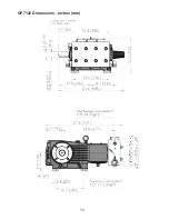
Page 15: ...15 GP7122 Dimensions Inches mm ...

Page 16: ... part 5 Changes or modifications made by the customer or third party 6 Theoperationofpumpsandoraccessoriesexceedingthespecificationssetforth in the Operations Manuals provided by Giant Industries Inc Liability under this warranty is on all non wear parts and limited to the replacement or repair of those products returned freight prepaid to Giant Industries which are deemed to be defective due to w...

Reviews: