background image

6

GP7136 HORSEPOWER REQUIREMENTS

RPM

GPM

1000 PSI

1400 PSI

2000 PSI

2500 PSI

3625 PSI

300

11.3

8.1

11.3

16.1

20.2

29.3

400

15.0

10.7

15.0

21.4

26.8

38.8

550

20.8

14.9

20.8

29.7

37.1

53.9

600

22.6

16.1

22.6

32.3

40.4

58.5

650

25.0

17.9

25.0

35.7

44.6

64.7

700

26.4

18.9

26.4

37.7

47.1

68.4

750

28.3

20.2

28.3

40.4

50.5

73.3


U.S.


Metric

Maximum Volume** .........................................................28.3 GPM  ....................................107 L/min

Maximum Discharge Pressure**......................................3625 PSI ..........................................250 Bar

Maximum Speed** ..................................................................................................................700 RPM

Inlet Pressure ..................................................................-4.35 to 145 PSI......................-0.3 to 10 Bar

Plunger Diameter.............................................................1.4” .....................................................36mm

Plunger Stroke .................................................................2.0” .....................................................52mm

Crankshaft Diameter........................................................1.9” .....................................................48mm

Key Width ........................................................................0.6” .....................................................14mm

Crankshaft Mounting ............................................................................................................Either side

Shaft Rotation ....................................................................................... Top of pulley towards manifold

Temperature of Pumped Fluids .......................................140 

o

F ..................................................60 

o

C

Inlet Ports .......................................................................................................................(2) 1 1/4” NPT

Discharge Ports .................................................................................................................(2) 3/4” NPT

Weight .............................................................................374 lbs. .............................................170 kg.

Crankcase Oil Capacity*..................................................1.6 gallons .......................................... 6.0 L.

Fluid End Material..........................................................................................................Stainless Steel

Volumetric Efficiency @ 700 RPM

 ................................................................................................. 94%

Mechanical Efficiency @ 700 RPM

 ............................................................................................... 83%

GP7136 Pump Specifications

HORSEPOWER RATINGS:

The rating shown are the power requirements 

for the pump.  Gas engine power outputs must 

be approximately twice the pump power require-

ments shown above.

We recommend a 1.15 service factor be speci-

fied when selecting an electric motor as the 

power source.   

To compute specific pump horsepower require

-

ments, use the following formula:


GPM X PSI

Consult the factory for special requirements that must be met if the 

pump is to operate beyond one or more of the limits specified above. 

Decible Chart


      1450

 hp =

*If the pump is mounted on a vehicle with the possibilty of unlevelness and/or the pump speed is between 300 and 500 

RPM, the volume of oil should be 1.93 gallons (7.3 liters). To check, put the oil dipstick in the bore situated next to the eye 

bolt.

**This figure is the maximum amount for this pump.  For continuous duty and/or with water warmer than 140 °F (60 °C), 

these values should be reduced by 10%.

Summary of Contents for GP7132

Page 1: ...nstallation Instructions page 2 GP7132 Pump Specifications page 3 Exploded View page 4 Parts List Kits page 5 GP7136 Pump Specifications page 6 Repair and Service pages 7 9 Torque Specs page 9 Trouble Shooting Chart page 10 Recommended Spare Parts List page 10 Dimensions page 11 Warranty Information back page ...

Page 2: ...bore situated next to the eye bolt 31 2 The inlet to the pump should be sized for the flow rate of the pump with no unnecessary restrictions that can cause cavitation Teflon tape should be used to seal all joints If pumps are to be operated at temperatures in excess of 140o F it is important to insure a positive head to the pump to prevent cavita tion 3 The discharge plumbing from the pump should ...

Page 3: ... gallons 6 0 L Fluid End Material Stainless Steel Volumetric Efficiency 700 RPM 94 Mechanical Efficiency 700 RPM 83 GP7132 Pump Specifications HORSEPOWER RATINGS The rating shown are the power requirements for the pump Gas engine power outputs must be approximately twice the pump power require ments shown above We recommend a 1 15 service factor be speci fied when selecting an electric motor as th...

Page 4: ...4 Exploded View GP7132 and GP7136 Pumps ...

Page 5: ...re Ring GP7132 3 41 06795 Pressure Ring GP7136 3 42 06096 V Sleeve GP7132 6 42 06796 V Sleeve GP7136 6 43 06097 Sleeve Support Ring GP7132 3 43 06797 Sleeve Support Ring GP7136 3 45 06098 Tension Spring 3 49 13159 Stud Bolt 8 49A 13160 Nut 8 50 06798 Valve Casing 1 51 04727 Inlet Valve Assembly 3 51B 05193 O Ring 3 51C 04725 Inlet Valve Seat 3 51D 13130 Valve Plate 3 51E 07062 0100 Valve Spring 3 ...

Page 6: ...Material Stainless Steel Volumetric Efficiency 700 RPM 94 Mechanical Efficiency 700 RPM 83 GP7136 Pump Specifications HORSEPOWER RATINGS The rating shown are the power requirements for the pump Gas engine power outputs must be approximately twice the pump power require ments shown above We recommend a 1 15 service factor be speci fied when selecting an electric motor as the power source To compute...

Page 7: ...Valve seats 51C and 52C are pressed out of spacer pipe 51F by hitting the valve plate 51D 52D with a bolt 4 Check surfaces of valve plate 51D 52D valve seat 51C 52C O rings 51B 52B and re place worn parts 5 When reassembling The suction valve seat 51C is 1mm smaller in diameter than the dis charge valve seat 52C Suction valve seats are marked S and always have to be installed first Discharge valve...

Page 8: ... 38A or support rings 38B are damaged replace with new parts 38A 38B 38 38B 38A 36 10 Take tension spring 45 and seal pack 41 42 43 out of seal sleeve Take a thin screw driver and pry out the grooved ring 39A Note This seal 39A will not be reusable so replace with a new part For the seal pack 41 43 remove with either a socket wrench or use a screw driver to push against the rear lip of the pressur...

Page 9: ...er removing the circlip ring 33B lever out seal retainer 33 with a screw driver Check seals 32 32A 33A and surfaces of crosshead 16 Remove crankcase cover 4 Loosen inner hexagon screws on the connecting rods 24 and push con rod halves as far into the crosshead guide as possible IMPORTANT Connecting rods are marked for identification Do not twist con rod halves Con Rod is to be reinstalled in the s...

Page 10: ...rop leaks correctly sized inlet plumbing to pump Accumulator pressure Recharge Replace accumulator Unloader Check for proper operation Cavitation Check inlet lines for restrictions and or proper size Pump Pressure as Restricted discharge plumbing Re size discharge plumbing to Drop at gun flow rate of pump Rated Pressure Excessive Worn plungers Replace plungers Leakage Worn packing seals Adjust or ...

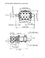
Page 11: ...11 GP7132 and GP7136 Dimensions Inches mm ...

Page 12: ...ormal wear and tear to standard wear parts 3 Use of repair parts other than those manufactured or authorized by Giant 4 Improper use of the product as a component part 5 Changes or modifications made by the customer or third party 6 The operation of pumps and or accessories exceeding the specifications set forth in the Operations Manuals provided by Giant Industries Inc Liability under this warran...

Reviews: