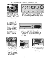
8. From the front of the manifold
(#43), remove the packing as
-
sembly (#41A, 41, 40, and 39).
Use a small slide hammer puller
if necessary, or insert a wooden
dowel through the back of the
manifold and tap the assembly
out from the back to the front.
9. Turn the manifold (#43) over and remove the rear v-sleeve
snap ring (#36) and rear v-sleeve assembly (#35A-35D).
These parts should slide out with little resistance. If neces-
sary, a screwdriver may be used to pry outward. Replace
all rubber parts and inspect the metal parts for wear.
36 35D 35A 35B 35C
10.
Note: The following pro-
cedure is only necessary
if a stud bolt (#49) has
been damaged and must
be replaced.
To remove
the manifold studs (#49),
place a stud nut (#50),
lock washer (#50A), and
second nut on each stud.
Tighten the nuts against
each other. Hold the front
nut with one wrench, and
remove the stud bolt by
turning the rear nut coun-
terclockwise with another
wrench. To reassemble,
turn the front stud bolt nut
clockwise.
11. Inspect ceramic plunger pipe (29B). Clean any dirt or
grime. If the surface of the pipe is rough, scored or pitted,
replace plunger pipe. To remove the ceramic plunger
pipe, turn the plunger bolt (#29C) counterclockwise with
a 13mm socket. Use a steady torque to prevent ceramic
plunger pipe damage. Loosen and remove the plunger
bolt assembly (#29C and #29D) and replace the seal
washer (#29D).
12. Inspect the crankcase oil
seals (#31) for evidence of
leaking. If there is oil on
the crankcase (#1) at the
sight of the oil seals, they
must be replaced. The oil
seals are replaced after
removing the crosshead/
plunger assembly (#25) as
described on page 9.
31
REPAIR INSTRUCTION - MP4120-SWS/MP4124-SWS
8
29C 29D 29B
13. Clean the bolt threads
(#29C), apply locktite,
and remount.
14. Torque the ceramic plunger
bolt assembly to 300 inch-
pounds (34 Nm). If origi
-
nally removed, reinstall the
stud bolts (#49).


