background image

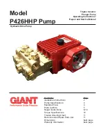
Model

P426HHP Pump

Contents: 

Page

Installation Instructions: 

Pump Specifications: 

3

Exploded View: 

Parts List/Kits: 

5

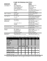
Repair Instructions: 

6-10

Torque Specifications 

10

Trouble Shooting Chart: 

11 

Recommended Spare Parts List: 

11 

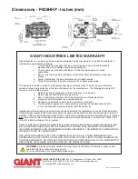
Dimensions: 

back page 

Warranty Information: 

back page 

Triplex Ceramic

Plunger Pump

Operating Instructions/ 

Repair and Service Manual

Hydraulic Drive Pump

Summary of Contents for P426HHP

Page 1: ...oded View 4 Parts List Kits 5 Repair Instructions 6 10 Torque Specifications 10 Trouble Shooting Chart 11 Recommended Spare Parts List 11 Dimensions back page Warranty Information back page Triplex Ceramic Plunger Pump Operating Instructions Repair and Service Manual Hydraulic Drive Pump ...
Page 2: ... explosive and toxic media the pump manufacturer must be consulted with regard to the resistance of the pump material It is the responsibility of the equipment manufacture and or operator to ensure that all pertinent safety regulations are adhered to Required NPSH refers to water specific weight 1kg dm3 viscosity 1 E and maximum premissible pump revolutions Operation and Maintenance Check oil leve...

Page 3: ...s RPM use the formula GPM 0 00986 x RPM U S Metric Flow continuous Up to 14 3 GPM 54 L min Flow intermittent 18 GPM 68 1 L min Maximum Discharge Pressure Up to 3000 PSI 200 bar Maximum Inlet Pressure 145 PSI 10 bar Power Required 27 1 BHP 20 7 kW Stroke 0 97 24 6 mm RPM continuous 1450 RPM RPM intermittent 1825 RPM Plunger Diameter 1 02 26 mm Temperature of Pumped Fluids Up to 160 o F 70 o C Inlet...

Page 4: ...4 P426HHP Pump Exploded View ...

Page 5: ...7023 O Ring 3 16F 07203 Backup Ring 3 16G 07258 Copper Washer 3 17 06790 Crosshead Pin 3 19 05444 Oil Seal 3 20 04654 Seal Case 3 20A 07266 O Ring 3 21 04655 Seal Sleeve 3 21A 07281 O Ring 6 21B 05967 Support Ring 6 22 04656 Drip Return Ring 3 23 04657 Grooved Seal 3 23A 04658 Support Ring 3 24 04657 Grooved Seal 3 24A 04660 Support Ring 3 25 04661 Seal Casing 1 25B 02009 O Ring 2 26 04662 Manifol...

Page 6: ... Note Always take time to lubricate all metal and nonmetal parts with a light film of oil before reassembly This step will ensure proper fit at the same time protecting the pump nonmetal parts i e the elastomers from cutting and scoring ...

Page 7: ...7 P426HHP Pump Repair Instructions ...

Page 8: ...8 P426HHP Pump Repair Instructions ...

Page 9: ...9 P426HHP Pump Repair Instructions ...

Page 10: ...s 12 Nm 5 07109 Oil Drain Plug 59 ft lbs 80 Nm 5B 08092 Plug with Gasket 59 ft lbs 80 Nm 6 01010 Screw 110 in lbs 12 5 Nm 10 07114 Screw with Washer 133 in lbs 15 Nm 15 08390 Connecting Rod Assembly 97 in lbs 11 Nm 16D 08399 Tensioning Screw Loctite 243 21 ft lbs 28 Nm 32 05971 Plug Loctite 243 107 ft lbs 145 Nm 34 05973 Cap Screw Lightly oil threads 30 ft lbs 40 Nm ...

Page 11: ... Accumulator pressure Recharge Replace accumulator Unloader Check for proper operation Cavitation Check inlet lines for restrictions and or proper size Pressure Drop at Gun Restricted discharge plumbing Re size discharge plumbing to flow rate of pump Excessive Worn plungers Replace plungers Leakage Worn packing seals Adjust or Replace packing seals Excessive vacuum Reduce suction vacuum Cracked pl...

Page 12: ...omponent part 5 Changes or modifications made by the customer or third party 6 The operation of pumps and or accessories exceeding the specifications set forth in the Operations Manuals provided by Giant Industries Inc Liability under this warranty is on all non wear parts and limited to the replacement or repair of those products returned freight prepaid to Giant Industries which are deemed to be...

Reviews: