background image

Contents:

Installation Instructions: 


page 2

Pump Specifications: 


page 3

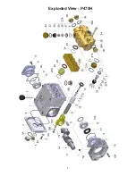
Exploded View: 


page 4

Parts List / Kits: 


page 5

Torque Specifications 


page 5

Repair Instructions: 


pages 6-7

Dimensions: 


back page

Warranty Information: 


back page

Triplex Ceramic

Plunger Pump

Operating Instructions/ 

Repair and Service Manual

Model

P470H

Hydraulic Drive Pump

Updated 04/22

Summary of Contents for P470H

Page 1: ...oded View page 4 Parts List Kits page 5 Torque Specifications page 5 Repair Instructions pages 6 7 Dimensions back page Warranty Information back page Triplex Ceramic Plunger Pump Operating Instructions Repair and Service Manual Model P470H Hydraulic Drive Pump Updated 04 22 ...

Page 2: ...e explosive and toxic media the pump manufacturer must be consulted with regard to the resistance of the pump material It is the responsibility of the equipment manufacture and or operator to ensure that all pertinent safety regulations are adhered to Required NPSH refers to water specific weight 1kg dm3 viscosity 1 E and maximum premissible pump revolutions Operation and Maintenance Check oil lev...

Page 3: ...8 7 2 9 7 14 5 19 6 1200 15 2 5 2 7 9 10 5 15 7 21 3 1300 16 5 5 7 8 5 11 4 17 1 23 1 1450 18 4 6 3 9 5 12 7 19 0 25 8 P470 HORSEPOWER REQUIREMENTS NOTE In order to drive the pump from the side opposite the present shaft extension simply remove the valve casing from the crankcase and rotate the pumps 180 degrees to the desired position Be certain to rotate the seal case item 20 as well so that the...

Page 4: ...4 Exploded View P470H ...
Page 5: ...asing 1 27A 04365 Valve Assembly 6 27 06937 Valve Seat 6 28 06938 Valve Plate 6 29 06959 Valve Spring 6 30 06939 Valve Spring Retainer 6 31 07212 O Ring 6 32 08373 Plug 3 33 07214 O Ring 3 34 06494 Cap Screw 8 36 07703 Plug 3 4 BSP 3 36A 04529 Copper Ring 3 Important If the pump is not used for a long period of time it is possible the seals 23 could become hard or brittle thus causing the pump to ...

Page 6: ...gs 21A 31 33 Replace worn parts Reassemble in same order Coat new o rings with oil before installation Coat O rings 25B with silicon grease and place them in their re cessses Insert seal cases 21 into valve casing 26 before mounting the whole unit Slide valve casing 26 over plungers Tighten hexagon socket screws 34 crosswise and evenly at 36 ft lbs Tighten plugs 32 at 125 ft lbs 170 Nm lmportant W...

Page 7: ...aring covers 7 8 onto the crankshaft ends Screw on bearing covers with screws 10 Mount connecting rod halves and tighten screws 15 at 22 ft lbs Mount crankcase cover 3 togeth er with O ring 4 Replace seal adaptors 20 seal casing 25 and valve casing 26 Replace eight 8 hexagon screws 34 and tighten to 30 ft lbs 40 Nm 9 Check plunger surfaces 16 Damaged surfaces lead to accelerated seal wear Deposits...

Page 8: ...ications made by the customer or third party 6 The operation of pumps and or accessories exceeding the specifications set forth in the Operations Manuals provided by Giant Industries Inc Liability under this warranty is on all non wear parts and limited to the replacement or repair of those products returned freight prepaid to Giant Industries which are deemed to be defective due to workmanship or...

Reviews: