7
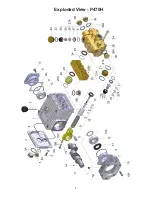
If oil leaks where the plungers (16) protrude out of the gear, gear seals (19) and plungers must
be examined and replaced if necessary.
a)
Gear Seal:
Remove oil plug (5) and drain oil. Remove valve casing (26) together with seal cas-
ing (25) as described above. Dismantle plunger pipe (I6B). Pry gear seal adaptor (20) out of the
crankcase using a screwdriver; take out gear seal (19) and replace it.
b)
Plungers:
Remove oil plug (5) and drain oil; remove crankcase cover (3). Remove valve casing
(26), seal casing 25), gear seal adaptors (20) and plunger pipes (16B) as described above. Remove
screws on conn-rods (15). Be careful not to mix up the connecting rod halves. Push connecting rod
shaft as far as possible into the crosshead guide. Take off screws (10) and pry out bearing covers (7
& 8) with the help of a screwdriver. Take out crankshaft carefully threading it past the conrods (15),
making sure not to bend the connecting rods. Remove and dismantle connecting rods and plung-
ers (16). Replace worn parts. Reassemble and tighten tension screws (16D) at 248 in.-lbs. (28 Nm).
When reinstalling, first insert connecting rods together with plungers. Thread in crankshaft. Then
push bearing covers (7 & 8) onto the crankshaft ends. Screw on bearing covers with screws (10).
Mount connecting rod halves and tighten screws (15) at 22 ft-lbs. Mount crankcase cover (3) togeth
-
er with O-ring (4). Replace seal adaptors (20), seal casing (25) and valve casing (26). Replace eight
(8) hexagon screws (34) and tighten to 30 ft.-lbs. (40 Nm).
9. Check plunger surfaces (16). Damaged surfaces
lead to accelerated seal wear. Deposits of all
kinds must be removed from the plungers.
16
REPAIR INSTRUCTIONS - P470H PUMPS
Important:
Plunger surfaces are not to be dam-
aged. If there are lime desposits in the pump,
care must be taken that the weep-return bore in
parts (25) and (26) ensure trouble-free weep-re-
turn.
10. If the plunger pipe (16B) is worn, remove
tension screw (16D) and remove together
with plunger pipe. Check and clean plung-
er (16A) surfaces and mount new plunger
pipe. Cover thread of tension screw (16D)
with a thin film of Loctite and tighten care
-
fully at 248 in.-lbs. (28 Nm).
Important:
Glue must never come be-
tween the plunger pipe (16B) and the
centring sleeve (16C). The plunger pipe is
not to be strained by eccentric tightening of
the tension screw or through damage to the
front surface as this can lead to breakage.
11. When reassembling, tighten inner
hexagon screw (34) at 30 ft.-lbs. (40
Nm) in a crossing pattern (as shown on
left).
Gear and Plunger
6
6
6
4
2 7
5
3
1
8
Summary of Contents for P470H
Page 4: ...4 Exploded View P470H ...


