background image

12

Gear End Disassembly

NOTE:  The manifold (29) weep seal housing (48) and spacer sleeve (26A) must be removed.  See above

for directions.

15. Remove the crankcase cover screws (9).  Inspect the crankcase cover o-ring  (4) for wear.  Replace if

necessary.

16. Inspect the dipstick (5) vent hole for signs of clogging.  Clean if necessary.

17. To remove the crankshaft (18), first remove the bearing cover plates (12).  Remove the key (19).

18. With a 5 mm allen wrench remove the connecting rod screws (21) and rear portion of connecting rod

assemblies (20).  Push the connecting rod (20) and plunger rod (22) down as far as possible into the
crankcase housing.

19. Hold the pump rear assembly with a wooden fixture, or other suitable device, in order to secure it while

removing the crankshaft (18).  Using a plastic mallet, tap the crankshaft from one side while turning it
from the other side.  The turning insures that during this sequence the crankshaft does not become
wedged against the front portion of the connecting rods (20).  The far side bearing (15) will remain in the
crankcase (1).  When free, the crankshaft can be removed by hand.  The opposite side crankshaft seal (14)
will be removed by this procedure.  

It is important that you turn the crankshaft (18) constantly while

tapping from the opposite end to avoid any binding.  The crankshaft bearing (15) remains on the
crankshaft as it is removed.  

If necessary, use a bearing puller to remove the crankshaft bearing (15).

20. Remove the front portion of the connecting rods (20) and plunger base assembly (22) from the rear of the

pump by pulling straight out of the crankcase crosshead guides.  

Notice that the connecting rod (20)

halves are numbered or colored. Connecting rods must be positioned with their numbers or colors
on the upper left-hand side, in the same numerical sequence as when they were removed.

21. Using a dowel and a rubber mallet, tap the oil seals (26) out from the rear of crankcase (1).  The area onto

which the oil seal rests should be clean and dry.  Put a small drop of loc-tite on the oil seals and place into
crankcase with lips facing the rear of the pump.

22. To remove the crosshead pin (23) from the crosshead (22), the assembly should be positioned on a

wooden fixture to avoid damage to crosshead.  Drive out the pin on opposite side of mark located on the
crosshead.  On those pumps without mark on crosshead, drive out pin by tapping on tapered side of pin.

23. To remove the bearing (15) remaining in the crankcase (1), insert small end of Giant bearing tool and tap

with a rubber mallet until bearing and seal (14) are completely removed.  

The bearing can only be

removed from the inside by inserting the Giant Bearing Tool through the opposite side of the
crankcase.  

The crosshead guide in the crankcase should be inspected for possible damage.

24. To reassemble, place the far bearing (15) in the crankcase (1) bearing housing and with the Giant Bearing

tool as a driver, tap into the crankcase using a rubber mallet.

25. Insert the far side crankshaft oil seal (14) with the Giant Bearing Tool making sure it is firmly seated and

well oiled.  Always make sure that the crankshaft seal lip does not show signs of wear and that the garter
spring is firmly in place on the seal before reinserting into the pump.  Replace the bearing cover (12) and
o-ring (13) and tighten securely.

Summary of Contents for P55W

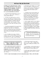
Page 1: ...n Instructions page 2 Pump Specifications pages 3 5 Exploded View page 6 Parts List page 7 Kits page 8 Trouble Shooting page 9 Repair Instructions page 10 13 Pump Mounting Selection Guide page 14 Recommended Spare Parts List page 14 Torque Specifications page 14 Dimensions page 15 Warranty Information back page ...

Page 2: ...y with any of these conditions invalidates the warranty 1 Prior to initial operation add oil to crankcase so that the oil level is between the two lines on the oil dipstick DO NOT OVERFILL Giant Recom mended Oil Crankcase oil should be changed after the first 50 hours of operation then at regular intervals of 500 hours or less depending on operat ing conditions recommended by Giant Industries Inc ...

Page 3: ...1420 RPM 0 94 Mechanical Efficiency 1420 RPM 0 86 Consult the factory for special requirements that must be met if the pump is to operate beyond one or more of the limits specified above Specifications Model P55W PULLEY INFORMATION Pulley selection and pump speed are based on a 1725 RPM motor and B section belts When selecting desired GPM allow for a 5 tolerance on pumps output due to variations i...

Page 4: ...kg Crankshaft Diameter 24mm Volumetric Efficiency 1420 RPM 0 94 Mechanical Efficiency 1420 RPM 0 86 Consult the factory for special requirements that must be met if the pump is to operate beyond one or more of the limits specified above Specifications Models P56W P56W HK PULLEY INFORMATION Pulley selection and pump speed are based on a 1725 RPM motor and B section belts When selecting desired GPM ...

Page 5: ...output due to variations in pulleys belts and motors among manufacturers 1 Select GPM required then select appropriate motor and pump pulley from the same line 2 The desired pressure is achieved by selecting the correct nozzle size that corresponds with the pump GPM 87000 GPM X PSI 1450 RPM NPSHR FT HEAD HORSEPOWER INFORMATION Horsepower ratings shown are the power require ments for the pump Gas e...

Page 6: ...6 Exploded View P55W P56W P56W HK P56HT ...

Page 7: ...sher 3 8 BSP except P56HT 1 P55W P56W P56W HK P56HT PARTS LIST ITEM PART DESCRIPTION QTY 1 07180 Crankcase 1 2 07181 Oil Filler Cap with Gasket 1 2A 07182 Gasket Oil Filler Cap 1 3 07183 Cover Crankcase 1 4 07184 O Ring Crankcase Cover 1 5 07185 Oil Dip Stick Assembly 1 6 01009 O Ring Dip Stick 1 7 07186 Oil Sight Glass 1 8 07187 Gasket Oil Sight Glass 1 9 07188 Screw Crankcase Cover 4 10 07223 Sp...

Page 8: ...Valve Spring S S 6 36 06016 Valve Plate 6 37 06014 Valve Seat 6 38 06015 O Ring 6 Plunger Packing Kit P55W 09088 Item Part Description Qty 31 07011 V Sleeve 3 Plunger Packing Kit P56W 09037 Item Part Description Qty 31 06076 V Sleeve 3 Plunger Packing Kit w Weep Seals P55W 09089 Item Part Description Qty 31 07011 V Sleeve Front 3 50 06241 Rear V Sleeve 3 51 06242 Support Ring 3 Plunger Packing Kit...

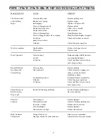
Page 9: ...case oil with recommended lubricant Cavitation Check inlet lines for restrictions and or proper sizing Rough Pulsating Worn packing Replace packing Operation with Inlet restriction Check system for stoppage air Pressure Drop leaks correctly sized inlet plumbing to pump Accumulator pressure Recharge Replace accumulator Unloader Check for proper operation Cavitation Check inlet lines for restriction...

Page 10: ... to 50 ft lbs 2 Remove the discharge spring retainer 34 valve spring 35 and valve plate 36 8 Inspect and clean the manifold and pressure ring Reinstall the pressure ring 30 with the groved side pointed towards the front Insert v sleeve 31 high temperature seals 31A for P56W HK P56HT pumps support ring 32 and pressure spring 33 into the manifold 29 30 32 33 4 Drain the oil from the pump Turn the pu...

Page 11: ...will melt any excess loc tite beneath the ceramic plunger allowing easy removal 12 Replace copper ring 24C onto plunger bolt 24B Slide plunger bolt assembly into ceramic plunger 24A Apply a light film of loc tite to plunger bolt threads and place plunger assembly onto stainless steel plunger base 22 and tighten to 105 in lbs 13 To replace plunger oil seals 26 proceed to Gear End Disassembly sectio...

Page 12: ...lling straight out of the crankcase crosshead guides Notice that the connecting rod 20 halves are numbered or colored Connecting rods must be positioned with their numbers or colors on the upper left hand side in the same numerical sequence as when they were removed 21 Using a dowel and a rubber mallet tap the oil seals 26 out from the rear of crankcase 1 The area onto which the oil seal rests sho...

Page 13: ...s when they were removed 28 Replace near side bearing 15 on crankshaft by using the Giant Bearing Tool and mallet to tap into place Take the crankshaft 18 end with the bearing 15 and insert the other end through the bearing housing and tap with a rubber mallet until the bearing is seated 29 When reassembling the connecting rods 20 note that the connecting rod halves are numbered or colored and tha...

Page 14: ...ron 1 gr AB Section 01062 7 75 Cast Iron 2 gr AB Section Rails 01034 Steel Box Rails L 9 25 x W 1 18 x H 1 62 01075 Plated Steel Channel Rails L 9 00 x W 2 12 x H 2 50 Preventative Maintenance Check List Recommended Spare Parts List Check Daily Weekly 50hrs Every Every Every 500 hrs 1500 hrs 3000 hrs Oil Level Quality X Oil Leaks X Water Leaks X Belts Pulley X Plumbing X Recommended Spare Parts Oi...

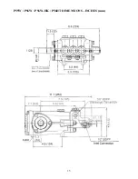
Page 15: ...15 P55W P56W P56W HK P56HT DIMENSIONS INCHES mm ...

Page 16: ...arty 2 Normal wear and tear to standard wear parts 3 Use of repair parts other than those manufactured or authorized by Giant 4 Improper use of the product as a component part 5 Changes or modifications made by the customer or third party 6 The operation of pumps and or accessories exceeding the specifications set forth in the Operations Manuals provided by Giant Industries Inc Liability under thi...

Reviews: