


U.S. ..................................... Metric
Flow .............................................................. 1.3 GPM ............................. 5.1 Liters/min.
Discharge Pressure (Continuous) ................. 5000 PSI ............................. 350 Bar
Discharge Pressure (Intermittent) ................. 6525 PSI ............................. 450 Bar
Max. Inlet Pressure ....................................... 145 PSI ............................... 10 Bar
Max. Crankshaft Speed .............................................................................. 1420 RPM
Plunger Diameter .......................................... 0.47” ................................... 12 mm
Stroke ............................................................ 0.56” ................................... 18.1 mm
Crankcase Oil Capacity ................................ 15.2 fl.oz. ............................ 0.45 Liters
Max. Temperature of Pumped Fluids ........... 160
o
F .................................. 70
o
C
Inlet Ports ................................................................................................... (2) 1/2" BSP
Discharge Ports ........................................................................................... (2) 3/8" BSP
Crankshaft Mounting .................................................................................. Either
Shaft Rotation ............................................... Top of Pulley Towards Fluid End
Weight ........................................................... 17.2 lbs. .............................. 7.8 Kg.
Crankshaft Diameter ..................................... 0.87” ................................... 22mm
Consult the factory for special requirements that must be met if the pump is to
operate beyond one or more of the limits specified above.
Specifications
Models P57 & P57-0011
PULLEY INFORMATION
Pulley selection and pump speed are based on a 1725
RPM motor and "B" section belts. When selecting
desired GPM, allow for a ±5% tolerance on pumps
output due to variations in pulleys, belts and motors
among manufacturers.
1.
Select GPM required, then select appropriate
motor and pump pulley from the same line.
2.
The desired pressure is achieved by selecting the
correct nozzle size that corresponds with the pump
GPM.
HORSEPOWER INFORMATION
Horsepower ratings shown are the power require-
ments for the pump. Gas engine power outputs must
be approximately twice the pump power require-
ments shown above.
We recommend that a 1.1 service factor be specified
when selecting an electric motor as the power source.
To compute specific pump horsepower requirements,
use the following formula:
GPM X PSI
=hp
1460
3
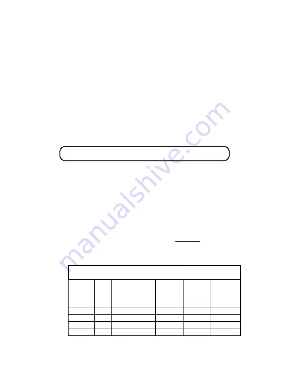
P57 PULLEY SELECTION & HORSEPOWER REQUIREMENTS
PUMP
PULLEY
RPM GPM 3000 PSI 4000 PSI 5000 PSI 6525 PSI*
7.75"
500
0.5
1.0
1.4
1.7
2.3
7.75"
750
0.7
1.4
1.9
2.4
3.2
7.75"
1000
0.9
1.9
2.5
3.1
4.1
7.75"
1250
1.1
2.3
3.0
3.8
5.0
7.75"
1420
1.3
2.7
3.6
4.5
5.9


