
10
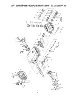
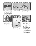
25. To reassemble, place the far bearing (15) in the crankcase (1) bearing housing and with the Giant Bearing
tool as a driver, tap into the crankcase using a rubber mallet.
26. Insert the far side crankshaft oil seal (14) with the Giant Bearing Tool making sure it is firmly seated and well
oiled. Always make sure that the crankshaft seal lip does not show signs of wear and that the garter spring
is firmly in place on the seal before reinserting into the pump. Replace the bearing cover (12) and o-ring (13)
and tighten securely.
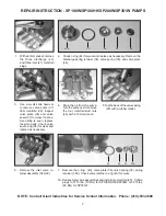
27. Replace the front portion of the connecting rod (20) and plunger rod/ crosshead assembly (22) by press-fitting
the crosshead pin (23). Make sure to insert the beveled edge of the crosshead pin into crosshead. If the
crosshead has a mark, install pin from marked side.
The crosshead pin (23) should not extend beyond
either side of the crosshead (22) in order to prevent damage to the crosshead bore of the crankcase
(1).
28. Place each crosshead/ plunger assembly into the pump making sure that all of the parts are well oiled before
insertion into the crankcase (1).
Notice that the connecting rod (20) halves are numbered or colored.
Connecting rods must be positioned with their numbers or colors on the upper left-hand side, in the
same numerical sequence as when they were removed.
29. Replace near side bearing (15) on crankshaft by using the Giant Bearing Tool and mallet to tap into place.
Take the crankshaft (18) end with the bearing (15) and insert the other end through the bearing housing and
tap with a rubber mallet until the bearing is seated.
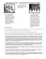
30. When reassembling the connecting rods (20), note that the connecting rod halves are numbered or colored
and that the numbers or colors must be matched and aligned. Torque the connecting rod bolts to 310 in.-lbs.
(35 Nm).
31. Insert the near side crankshaft oil seal (14) with the Giant Bearing Tool making sure it is firmly seated and well
oiled. Replace the bearing cover (12) and o-ring (13) and tighten securely.
See steps 7A-15 above for re-installing fluid end onto the gear end.
32. Fill the crankcase (1) with 24 oz. (0.7 liters) of Giant Industries’ oil and check the oil level with the dipstick (5).
Proper level is center of two lines. Reinstall the pump into your system.
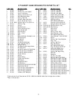
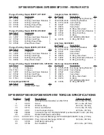
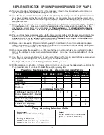
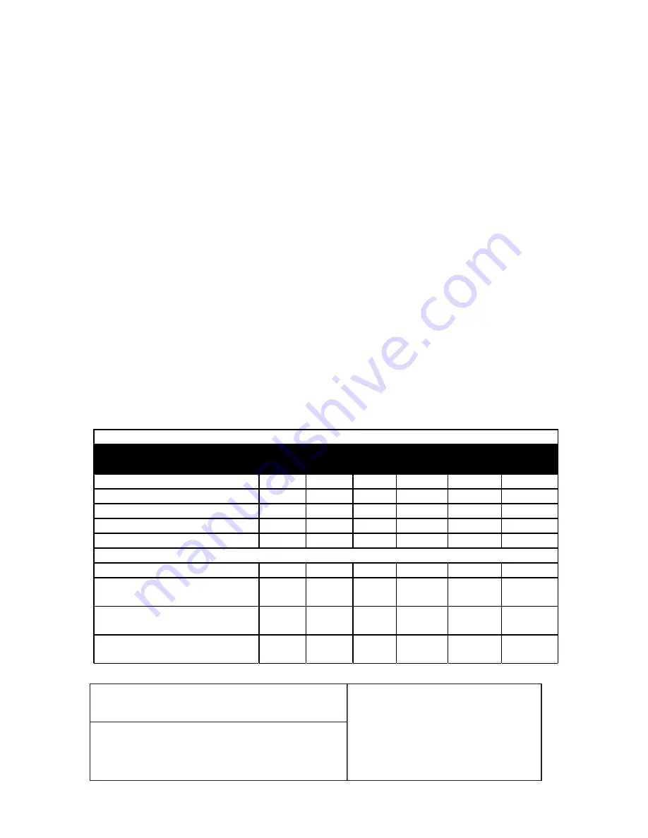
Pump Mounting Selection Guide
Bushings
07175
- 28 mm Tapered H Bushing
Pulley & Sheaves
01055
- 9.75” Cast Iron 2 gr. - AB Section
01062
- 7.75” Cast Iron - 2 gr. - AB Section
Rails
07358
- Plated Steel Channel Rails
(L=9.18” x W=1.88” x H=3.00”)
Check
Daily Weekly 50 Hrs. Every
500 hrs
Every
1500 hrs
Every
3000 hrs
Oil Level/Quality
X
Oil Leaks
X
Water Leaks
X
Belts, Pulley
X
Plumbing
X
Oil Change (1 quart) p/n 01154
X
X
Plunger Packing Kit (1 kit/pump)
See page 6 for kit list
X
Valve Assembly Kit (1 kit/pump)
See page 6 for kit list
X
Oil Seal Kit (1 kit/pump)
See page 6 for kit list
X
Preventative Maintenance Check List & Recommended Spare Parts List
Recommended Spare Parts
REPAIR INSTRUCTION - SP100W/SP100HK/SP200W/SP351W PUMPS
7
7
7


