background image

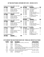
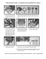
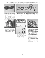
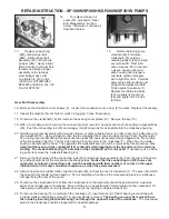
03/18   SP100W(HK)_SP200W_SP351W.indd

GIANT INDUSTRIES, INC.

, 900 N. Westwood Ave., Toledo, Ohio  43607

Phone:  (419) 531-4600    FAX (419) 531-6836, www.giantpumps.com

 

Copyright 2018 Giant Industries, Inc.

GIANT INDUSTRIES LIMITED WARRANTY

Giant Industries, Inc. pumps and accessories are warranted by the manufacturer to be free from 

defects in workmanship and material as follows:


1.  For portable pressure washers and self-service car wash applications, the discharge  


manifolds will never fail, period. If they ever fail, we will replace them free of charge.  


Our other pump parts, used in portable pressure washers and in car wash applications, 

aaaaaaaaaaa

are warranted for five years from the date of shipment for all pumps used in NON-   


SALINE, clean water applications.


2.    One (1) year from the date of shipment for all other Giant industrial and consumer    


 pumps.


3.    Six (6) months from the date of shipment for all rebuilt pumps.


4.    Ninety (90) days from the date of shipment for all Giant accessories.


This warranty is limited to repair or replacement of pumps and accessories of which the  manufac

-

turer’s evaluation shows were defective at the time of shipment by the manufacturer.  The following 

items are NOT covered or will void the warranty:


1.   Defects caused by negligence or fault of the buyer or third party.


2.    Normal wear and tear to standard wear parts.


3.   Use of repair parts other than those manufactured or authorized by Giant.


4.   Improper use of the product as a component part.


5.   Changes or modifications made by the customer or third party.


6.   The operation of pumps and or accessories exceeding the specifications set forth    


in the Operations Manuals provided by Giant Industries, Inc.

Liability under this warranty is on all non-wear parts and limited to the replacement or repair of those 

products returned freight prepaid to Giant Industries which are deemed to be defective due to work

-

manship or failure of material.  A Returned Goods Authorization (R.G.A.) number and completed 

warranty evaluation form is required prior to the return to Giant Industries of all products under 

warranty consideration.  Call (419)-531-4600 or fax (419)-531-6836 to obtain an R.G.A. number.

Repair or replacement of defective products as provided is the sole and exclusive remedy provided 

hereunder and the MANUFACTURER SHALL NOT BE LIABLE FOR FURTHER LOSS, DAMAGES, 

OR EXPENSES, INCLUDING INCIDENTAL AND CONSEQUENTIAL DAMAGES DIRECTLY OR 

INDIRECTLY ARISING FROM THE SALE OR USE OF THIS PRODUCT.

THE LIMITED WARRANTY SET FORTH HEREIN IS IN LIEU OF ALL OTHER WARRANTIES OR 

REPRESENTATION, EXPRESS OR IMPLIED, INCLUDING WITHOUT LIMITATION ANY WAR-

RANTIES OR MERCHANTABILITY OR FITNESS FOR A PARTICULAR PURPOSE AND ALL SUCH 

WARRANTIES ARE HEREBY DISCLAIMED AND EXCLUDED BY THE MANUFACTURER.


Summary of Contents for SP100HK

Page 1: ...ploded View Kits page 6 Repair Instructions pages 7 10 Recommended Spare Parts List page 10 Pump Mounting Selection Guide page 10 Dimensions page 11 Warranty Information back page Models SP100W SP100HK SP200W SP351W Triplex Ceramic Plunger Pump Operating Instructions Repair and Service Manual Updated 03 18 ...

Page 2: ...driven shaft side and coupling by a contact protector Pressure in discharge line and in pump must be at zero before any maintenance to the pump takes place Close up suction line Disconnect fuses to ensure that the driving motor does not get switched on accidently Make sure that all parts on the pressure side of the unit are vented and refilled with pres sure at zero before starting the pump In ord...

Page 3: ...n above We recommend that a 1 1 service factor be speci fied when selecting an electric motor as the power source To compute specific pump horsepower requirements use the following formula GPM X PSI 1450 HP Max Flow Maximum Pressure Max Speed Power Required Max Temp Plunger Diameter Stroke Model GPM PSI RPM HP F in in SP100W 11 2 1885 1420 14 6 160 1 02 0 79 SP100HK 11 2 1885 1420 14 6 195 1 02 0 ...

Page 4: ...4 SP100W SP100HK SP200W SP351W Exploded View ...

Page 5: ...K 3 ITEM PART DESCRIPTIONS QTY 31 06083 V Sleeve SP200W 3 31 07322 V Sleeve SP351W 3 31A 11503 V Sleeve SP100HK 3 32 07337 Support Ring SP100W 3 32 13367 Support Ring SP200W 3 32 07270 Support Ring SP351W 3 33 07338 Pressure Spring SP100W HK SP200W 3 33 07275 Pressure Spring SP351W 3 34 07325 Spring Retainer Discharge 3 34A 07326 0100 Spring Retainer Inlet 3 35 07312 0100 Valve Spring 6 36 07327 V...

Page 6: ...Ring Valve Seat 6 40 12057 O Ring Inlet Valve Retainer 3 42 07332 O Ring Inlet Plug 3 44 07214 O Ring SP100W HK SP200W 3 44 07035 O Ring SP351W 3 Inlet Valve Kit 09069 ItemPart Description Qty 34A 07326 0100 Inlet Spring Retainer 3 35 07312 0100 Valve Spring 3 36 07327 Valve Plate 3 37 06014 Valve Seat 3 38 06015 O Ring Valve Seat 3 40 12057 O Ring Inlet Valve Retainer 3 42 07332 O Ring Inlet Plug...

Page 7: ... and valve seats 37 for wear If exces sive pitting is seen replace the worn parts Check valve seat o ring 38 for wear and replace as necessary 4 Drain the oil from the pump Turnthepumpovertoremove the four manifold stud nuts 46 with a 19mm wrench 41A 44 34 35 36 6 Remove the inlet valve re tainer assembly 34A 39 7 Remove the o ring 40 valve plate 36 valve spring 35 spring retainer 34A Check valve ...

Page 8: ...check for wear 11 Inspect seals 50 seal sup port ring 51 and O ring 49 and replace as necessary 49 50 51 12 Inspect ceramic plunger 24A tips for wear If neces sary replacement of the ceramic plungers may be ac complished by removing the plunger bolt assemblies 24 with a 13mm wrench Ce ramic plungers should now slide off the stainless steel plunger base 22 Exces sive resistance to plunger removal m...

Page 9: ... removed 22 Using a dowel and a rubber mallet tap the oil seals 26 out from the rear of crankcase 1 The area onto which the oil seal rests should be clean and dry Put a small drop of loc tite on the oil seals and place into crankcase with lips facing the rear of the pump 23 To remove the crosshead pin 23 from the crosshead 22 the assembly should be positioned on a wooden fixture to avoid damage to...

Page 10: ... Tool and mallet to tap into place Take the crankshaft 18 end with the bearing 15 and insert the other end through the bearing housing and tap with a rubber mallet until the bearing is seated 30 When reassembling the connecting rods 20 note that the connecting rod halves are numbered or colored and that the numbers or colors must be matched and aligned Torque the connecting rod bolts to 310 in lbs...

Page 11: ...11 SP100W SP100HK SP200W SP351W DIMENSIONS INCHES mm ...

Page 12: ...party 2 Normal wear and tear to standard wear parts 3 Use of repair parts other than those manufactured or authorized by Giant 4 Improper use of the product as a component part 5 Changes or modifications made by the customer or third party 6 The operation of pumps and or accessories exceeding the specifications set forth in the Operations Manuals provided by Giant Industries Inc Liability under th...

Reviews: