background image

6

Plunger Packing Repair #09077, SP100W

Item Part # 

Description 

Qty.

31  07336 

V-Sleeve 

3

40  12057 

O-Ring, Inlet Valve Retainer  3

42  07332 

O-Ring, Inlet Plug 

3

49  07344 

O-Ring, Weep Plate 

1

50  07336 

Weep Return Seal 

Plunger Packing Repair #09798, SP200W

Item Part # 

Description 

Qty.

31  06083 

V-Sleeve 

3

40  12057 

O-Ring, Inlet Valve Retainer  3

42  07332 

O-Ring, Inlet Plug 

3

49  07344 

O-Ring, Weep Plate 

1

50  07688 

Weep Return Seal 

Plunger Packing Repair #09076, SP351W

Item Part # 

Description 

Qty.

31  07322 

V-Sleeve 

3

40  12057 

O-Ring, Inlet Valve Retainer  3

42  07332 

O-Ring, Inlet Plug 

3

49  07344 

O-Ring, Weep Plate 

1

50  06064 

Weep Return Seal 

3

Plunger Packing Repair Kit #09077-HK, SP100HK

Item Part # 

Description 

Qty.

31  07336 

V-Sleeve 

3

31A 11503 

V-Sleeve 

3

40  12057 

O-Ring, Inlet Valve Retainer  3

42  07332 

O-Ring, Inlet Plug 

3

49  07344 

O-Ring, Weep Plate 

1

50  11503 

V-Sleeve 

Oil Seal Repair #09797

Item Part # 

Description 

Qty.

26  07318 

Radial Shaft Seal 

3

Complete Valve Kit #09814

Item Part # 

Description 

Qty.

34  07325  

Discharge Spring Retainer  3 

34A 07326-0100  Inlet Spring Retainer 

3

35  07312-0100  Valve Spring 

6

36  07327 

Valve Plate 

6

37  06014 

Valve Seat 

6

38  06015 

O-Ring, Valve Seat 

6

40  12057 

O-Ring, Inlet Valve Retainer  3

42  07332 

O-Ring, Inlet Plug 

3

44  07214 

O-Ring, 


SP100W(HK)/SP200W 

3

44  07035 

O-Ring, SP351W 

3

Inlet Valve Kit #09069

Item Part # 

Description 

Qty.

34A 07326-0100  Inlet Spring Retainer 

3

35  07312-0100  Valve Spring 

3

36  07327 

Valve Plate 

3

37  06014 

Valve Seat 

3

38  06015 

O-Ring, Valve Seat 

3

40  12057 

O-Ring, Inlet Valve Retainer  3

42  07332 

O-Ring, Inlet Plug 

3

Discharge Valve Kit #09068

Item Part # 

Description 

Qty.

34  07325-0100  Discharge Spring Retainer  3

35  07312-0100  Valve Spring 

3

36  07327 

Valve Plate 

3

37  06014 

Valve Seat 

3

38  06015 

O-Ring, Valve Seat 

3

44  07214 

O-Ring, 


SP100W(HK)/SP200W 

3

44  07035 

O-Ring, SP351W 

3

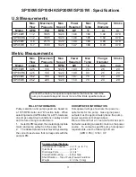
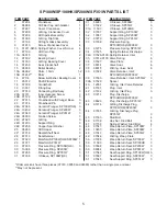
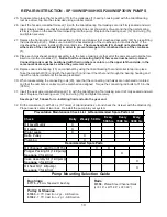
SP100W/SP100HK/SP200W/SP351W - REPAIR KITS

SP100W/SP100HK/SP200W/SP351W TORQUE SPECIFICATIONS

 Position 

Part# 

Description 

Torque Amount


07186 

Oil Sight Glass Assembly (Loctite 5910) 

106 in.-lbs. (12 Nm)

  9 

01010 

Screw 

221 in.-lbs. (25 Nm)

  11 

07109 

Oil Drain Plug 

29 ft.-lbs. (40 Nm)

  16 

07114 

Screw and Washer 

132 in.-lbs. (15 Nm)

  20A 

07311 

Inner Hexagon Screw 

22 ft.-lbs. (30 Nm)

  24B 

08399 

Tension Screw, SP100(HK)/SP200W (Loctite 243) 247 in.-lbs. (28 Nm)

  26 

07318 

Radial Shaft Seal (Loctite 403) 

  41/43 

07331/07213  Plug, Inlet and Discharge, SP100W(HK)/SP200W 51 ft.-lbs. (70 Nm)

  41/43 

07331/06800  Plug, Inlet and Discharge, SP351W 

59 ft.-lbs. (80 Nm)

  45 

07333 

Stud Bolt (Loctite 270)

  46 

07158 

Nut, Stud Bolt 

200 in.-lbs. (22.5 Nm)


Summary of Contents for SP100HK

Page 1: ...ploded View Kits page 6 Repair Instructions pages 7 10 Recommended Spare Parts List page 10 Pump Mounting Selection Guide page 10 Dimensions page 11 Warranty Information back page Models SP100W SP100HK SP200W SP351W Triplex Ceramic Plunger Pump Operating Instructions Repair and Service Manual Updated 03 18 ...

Page 2: ...driven shaft side and coupling by a contact protector Pressure in discharge line and in pump must be at zero before any maintenance to the pump takes place Close up suction line Disconnect fuses to ensure that the driving motor does not get switched on accidently Make sure that all parts on the pressure side of the unit are vented and refilled with pres sure at zero before starting the pump In ord...

Page 3: ...n above We recommend that a 1 1 service factor be speci fied when selecting an electric motor as the power source To compute specific pump horsepower requirements use the following formula GPM X PSI 1450 HP Max Flow Maximum Pressure Max Speed Power Required Max Temp Plunger Diameter Stroke Model GPM PSI RPM HP F in in SP100W 11 2 1885 1420 14 6 160 1 02 0 79 SP100HK 11 2 1885 1420 14 6 195 1 02 0 ...

Page 4: ...4 SP100W SP100HK SP200W SP351W Exploded View ...

Page 5: ...K 3 ITEM PART DESCRIPTIONS QTY 31 06083 V Sleeve SP200W 3 31 07322 V Sleeve SP351W 3 31A 11503 V Sleeve SP100HK 3 32 07337 Support Ring SP100W 3 32 13367 Support Ring SP200W 3 32 07270 Support Ring SP351W 3 33 07338 Pressure Spring SP100W HK SP200W 3 33 07275 Pressure Spring SP351W 3 34 07325 Spring Retainer Discharge 3 34A 07326 0100 Spring Retainer Inlet 3 35 07312 0100 Valve Spring 6 36 07327 V...

Page 6: ...Ring Valve Seat 6 40 12057 O Ring Inlet Valve Retainer 3 42 07332 O Ring Inlet Plug 3 44 07214 O Ring SP100W HK SP200W 3 44 07035 O Ring SP351W 3 Inlet Valve Kit 09069 ItemPart Description Qty 34A 07326 0100 Inlet Spring Retainer 3 35 07312 0100 Valve Spring 3 36 07327 Valve Plate 3 37 06014 Valve Seat 3 38 06015 O Ring Valve Seat 3 40 12057 O Ring Inlet Valve Retainer 3 42 07332 O Ring Inlet Plug...

Page 7: ... and valve seats 37 for wear If exces sive pitting is seen replace the worn parts Check valve seat o ring 38 for wear and replace as necessary 4 Drain the oil from the pump Turnthepumpovertoremove the four manifold stud nuts 46 with a 19mm wrench 41A 44 34 35 36 6 Remove the inlet valve re tainer assembly 34A 39 7 Remove the o ring 40 valve plate 36 valve spring 35 spring retainer 34A Check valve ...

Page 8: ...check for wear 11 Inspect seals 50 seal sup port ring 51 and O ring 49 and replace as necessary 49 50 51 12 Inspect ceramic plunger 24A tips for wear If neces sary replacement of the ceramic plungers may be ac complished by removing the plunger bolt assemblies 24 with a 13mm wrench Ce ramic plungers should now slide off the stainless steel plunger base 22 Exces sive resistance to plunger removal m...

Page 9: ... removed 22 Using a dowel and a rubber mallet tap the oil seals 26 out from the rear of crankcase 1 The area onto which the oil seal rests should be clean and dry Put a small drop of loc tite on the oil seals and place into crankcase with lips facing the rear of the pump 23 To remove the crosshead pin 23 from the crosshead 22 the assembly should be positioned on a wooden fixture to avoid damage to...

Page 10: ... Tool and mallet to tap into place Take the crankshaft 18 end with the bearing 15 and insert the other end through the bearing housing and tap with a rubber mallet until the bearing is seated 30 When reassembling the connecting rods 20 note that the connecting rod halves are numbered or colored and that the numbers or colors must be matched and aligned Torque the connecting rod bolts to 310 in lbs...

Page 11: ...11 SP100W SP100HK SP200W SP351W DIMENSIONS INCHES mm ...

Page 12: ...party 2 Normal wear and tear to standard wear parts 3 Use of repair parts other than those manufactured or authorized by Giant 4 Improper use of the product as a component part 5 Changes or modifications made by the customer or third party 6 The operation of pumps and or accessories exceeding the specifications set forth in the Operations Manuals provided by Giant Industries Inc Liability under th...

Reviews: