
9
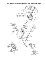
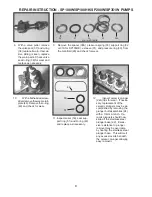
Gear End Disassembly
16. Remove the crankcase cover screws (9). Inspect the crankcase cover o-ring (4) for wear. Replace if necessary.
17. Inspect the dipstick (5) vent hole for signs of clogging. Clean if necessary.
18. To remove the crankshaft (18), first remove the bearing cover plates (12). Remove the key (19).
19. With a 5 mm allen wrench remove the connecting rod screws (21) and rear portion of connecting rod assemblies
(20). Push the connecting rod (20) and plunger rod (22) down as far as possible into the crankcase housing.
20. Hold the pump rear assembly with a wooden fixture, or other suitable device, in order to secure it while removing
the crankshaft (18). Using a plastic mallet, tap the crankshaft from one side while turning it from the other side.
The turning insures that during this sequence the crankshaft does not become wedged against the front portion
of the connecting rods (20). The far side bearing (15) will remain in the crankcase (1). When free, the crank-
shaft can be removed by hand. The opposite side crankshaft seal (14) will be removed by this procedure.
It is
important that you turn the crankshaft (18) constantly while tapping from the opposite end to avoid any
binding. The crankshaft bearing (15) remains on the crankshaft as it is removed.
If necessary, use a bear-
ing puller to remove the crankshaft bearing (15).
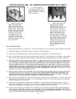
21. Remove the front portion of the connecting rods (20) and plunger base assembly (22) from the rear of the pump
by pulling straight out of the crankcase crosshead guides.
Notice that the connecting rod (20) halves are
numbered or colored. Connecting rods must be positioned with their numbers or colors on the upper
left-hand side, in the same numerical sequence as when they were removed.
22. Using a dowel and a rubber mallet, tap the oil seals (26) out from the rear of crankcase (1). The area onto which
the oil seal rests should be clean and dry. Put a small drop of loc-tite on the oil seals and place into crankcase
with lips facing the rear of the pump.
23. To remove the crosshead pin (23) from the crosshead (22), the assembly should be positioned on a wooden
fixture to avoid damage to crosshead. Drive out the pin on opposite side of mark located on the crosshead. On
those pumps without mark on crosshead, drive out pin by tapping on tapered side of pin.
24. To remove the bearing (15) remaining in the crankcase (1), insert small end of Giant bearing tool and tap with
a rubber mallet until bearing and seal (14) are completely removed.
The bearing can only be removed from
the inside by inserting the Giant Bearing Tool through the opposite side of the crankcase.
The crosshead
guide in the crankcase should be inspected for possible damage.
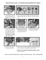
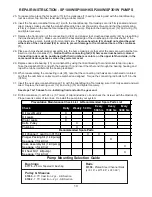
13.
Replace copper ring
(24E) onto plunger bolt
(24B). Slide plunger bolt
assembly (24) into ceramic
plunger (24A). Apply a light
film of loc-tite to plunger bolt
threads and place plunger
assembly onto stainless
steel plunger base (22)
and tighten to 310 in.-lbs.
(35 Nm) for SP100W(HK)/
SP200W and 265 in.-lbs. (30
Nm) for SP351W.
24E
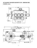
15.
Before replacing pump
manifold (29), first rotate
crankshaft (18) until two
outside plungers (24A) extend
evenly forward. Next lubri-
cate v-sleeves (50) in the rear
v-sleeve housing (48) and
slide housing over plungers.
Lubricate ceramic plungers
with a light film of oil. Carefully
and evenly slide manifold over
plungers and press manifold
firmly against crankcase (1).
Replace manifold stud bolts
(45), washers (47) and nut
(46) and tighten to 59 ft.-lbs.
(80 Nm).
14.
To replace plunger oil
seals (26), proceed to “Gear
End Disassembly” section
below. Otherwise, continue as
described below.
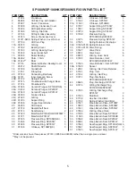
REPAIR INSTRUCTION - SP100W/SP100HK/SP200W/SP351W PUMPS


