


13
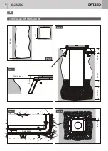
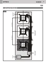
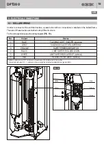
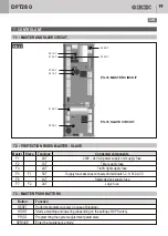
5.4 - INSERTING THE BOLLARD ON SLAB
5.5 - INSERTING THE BOLLARD
In case of laying on slab
(PIC. 7)
it is necessary to purchase the specific "kit for installation on slab". The instructions
are as follows:
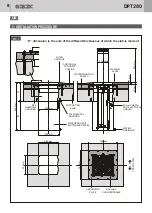
1.
Mark the laying point of each bollard, then remove the road surface/concrete casting for about
mm 1000 x 1000
.
Remove the waterproofing sheath in the middle of the laying point for about mm 500 x 500; take into consideration
the consecutive restoration .
2.
At the moment of purchasing, communicate the thickness of the slab in order to let the manufacturer produce
a stainless steel waterproof pit of a suitable length
ref. A and B
.
3.
In the center of the laying point remove the slab by drilling a
through hole of about mm 450 x 450 mm
.
4.
Place the counterframes equipped with anchoring plate in the center of the through hole. Secure it by means of
12 M16 chemical anchors
(supplied by the building contractor) complete with supplementary nuts for the proper
leveling of the counterframe/anchoring plate with respect to the walking level (to limit rainwater infiltrations into
the pit, arrange the counterframe approx.
10 mm
higher than the walking level ).
5.
Restore the waterproofing sheath, the additional concrete casting and the road surface.
6.
By means of
8 M8 chemical anchor
s (supplied by the contractor), secure the stainless steel waterproof pits to the
ceiling of the basement).
7.
Lay the pipes for the electrical cables from the bollards to the control unit.
8.
Lay the pipes for rainwater drainage from the waterproof pits to the drainage area.
9.
Lay the additional pipes from the control unit to the installation point of the accessories (i.e. inductive loops, traffic
lights, consolle, etc.). Prearrange the electrical connection and the earthing to the control unit.
(PIC. 7,
)
All the pipelines shall be laid in full compliance with the regulations in force.
1.
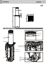
Keep the bollard ready in the immediate vicinity of the foundation box.
2.
Completely extend the cables on the ground to avoid possibile twisting.
3.
Lay the connecting cable for each bollard through the tube to the control unit .
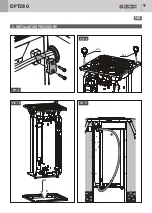
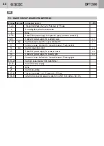
4.
Lay the connecting cable in the foundation box through the strain relief provided
(PIC. 8)
.
ATTENTION!
The function of the bollard may be impaired if the connecting cable is attached at a different point.
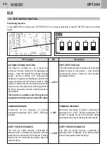
5.
Screw the four M16 eye bolts (not included in the bollard scope of delivery) into the prepared threaded holes
(PIC. 9)
.
6.
Fasten the strap, chains etc. onto the eye bolts and raise the bollard. Please observe the min. carrying capacity!
Gently place the bollard in the foundation box o
(PIC. 10)
.
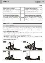
ATTENTION!
The function of the bollard may be impaired if the connecting cable is twisted.
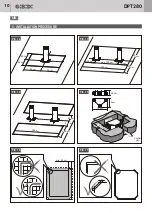
7.
While inserting the bollard into foundation box, avoid tight winding when laying the connecting cable in the
foundation box. Make sure that the lines are not clamped
(PIC. 11)
.
ATTENTION!
While inserting the bollard into the foundation box, make sure not to twist the cables nor to crush
them.
DPT280
UK


