


14
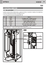
5.6 - LAYING THE INDUCTION LOOPS
If the system is used in the automatic operating mode (extension of bollard after a vehicle has driven
through), induction loops must be laid to detect metal masses (vehicles).
Induction loops are suitable for two different applications:
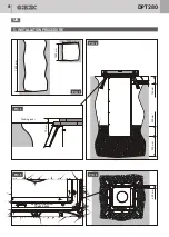
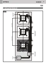
• "Limited" protection of the bollards
(PIC 12 - PIC. 13)
. In this case a single inductive loop is installed around
the bollards, it avoids the raising in case a vehicle is over the bollards or in the immediate surroundings.
• "Extended" protection of the bollards
(PIC. 14)
. Two induction loops, one before and one after the bollards, are laid
for added protection. A passing vehicle is identified approx. 3000 mm in front of the bollards and detected
to approx. 3000 mm behind the bollards. This allows the following vehicles to be identified in advance and thus
to prevent possible collisions.
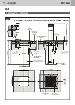
Notes on laying the induction loops:
1.
Standard induction loops are 9.60 m long (1800 × 3000 mm). Other lengths are also available.
2.
Induction loops consist of a special cable with approx. Ø 9 mm. These are suitable for direct laying in the ground
without sheathing or other protective equipment.
3.
Ensure that there is no reinforcing steel mesh when laying the induction loop. If a reinforcing steel mesh is present,
remove it up to approx. 25 cm above the circumference of the induction loop
(PIC. 16)
.
4.
Make sure that the corners are rounded when laying the induction loop”
(PIC. 16 - PIC. 17)
.
5.
Lay the induction loop 7 cm beneath the ground surface. In case of paving stones with a thickness of at least
10 cm, the material must be adjusted to permit laying at the specified depth. Alternatively, you can lay the
induction loop between paving stones in a diagonal join.
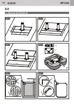
6.
Induction loops are equipped with a connection box
(PIC. 15)
to which the connecting cable for signa transmission
to the control is connected. The connecting cable consists of a strong, special cable with a standard length
of 15 m. (you can also order induction loops with a longer connecting cable ).
7.
You can also use induction loops to detect an exiting vehicle and for automatic requests to lower the bollard.
DPT280
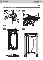
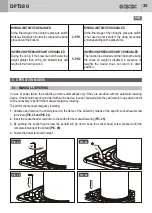
8.
Remove the eye bolts as soon as the bollard is positioned. Screw the bollard tight with the nuts supplied then apply
the plastic caps supplied on the top of the screws.
9.
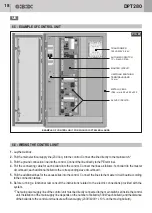
Carry out the basic electrical connections of the control unit as indicated in chpt. 6.2.
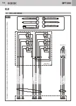
WARNING!
When connecting the bollard to the control unit carefully read the wiring diagrams contained in the
scope of delivery.
10. The control unit, configured according to the customer's needs as described in the order sheet,
is supplied with all the necessary wiring diagrams, including the electrical connections of the bollard.
UK


