

15
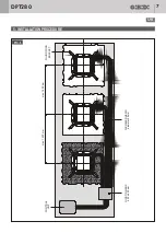
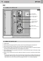
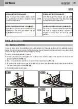
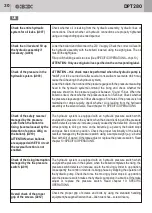
In order to connect all the electrical devices, a passive box with six connections is installed on the bollard frame.
The wires of these devices are marked out by different colours.
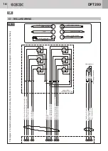
For the correspondence see the wiring diagram
(PIC. 19 )
.
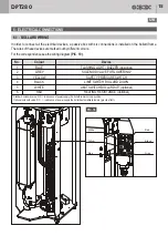
6 - ELECTRICAL CONNECTIONS
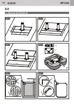
6.1 - BOLLARD WIRING
No.
1
2
3
4
5
6
Colour
BLUE
GREY
YELLOW
BLACK
WHITE
RED
Device
FLASHING LIGHT / BUZZER (opzional)
SOLENOID VALVE FOR LOWERING*
SAFETY PRESSURE SWITCH
LIMIT SWITCH BOLLARD DOWN
LIMIT SWITCH BOLLARD UP (optional)
HEATING RESISTANCE (optional)
*
Standard solenoid valve: N.C. = in absence of power supply the bollard remains in up position.
Optional solenoid valve
:
N
.
O
. =
(
gravity effect).
in absence of power supply the bollard automatically lowers
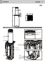
White
Yellow
Blue
Red
Black
Grey
PIC. 18
DPT280
UK


