24
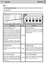
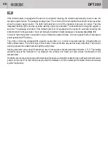
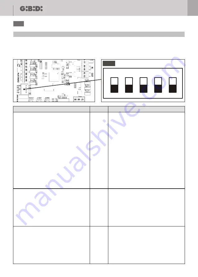
7.8 - FDIP SWITCH FUNCTION
Preliminary remarks:
on the MASTER circuit there are 5 DIP SWITCH; for a proper positioning of the DIP SWITCH refer to the chart
below.
AUTOMATIC RISING FUNCTION
The bollard is normally up - as a result of a
command it lowers, waiting for the passage of a
vehicle – once the vehicle has passed through
(safety devices enabled and subsequently
disabled), the system automatically performs the
rising procedure and the bollard returns to high
position. If within 30s since the bollard is down no
transit occurs, the system automatically performs
the rising procedure and the bollard returns to
high position.
This function is available only if the system is
equipped with safety devices and traffic lights.
STEP-STEP FUNCTION
The bollard after the first command, from the high
position moves to low position – after another
command the device returns to high position
(step/step function).
COMNAND ENABLED
Commands for the operation of bollard,
connected to terminals 24/25 - 26/27 - 58/59 are
enabled.
SAFETY DEVICES ENABLED
The inlet for safety devices, connected to
terminals 20/21 is enabled for operation with the
safety devices connected to the system. If safety
devices are not connected the system does not
allow the rising.
COMMAND DISABLED
Movement commands of bollard, connected to
terminals 24/25 - 26/27 - 58/59 are disabled. This
function is usually set by the technician during
maintenance to prevent unexpected commands.
SAFETY DEVICES DISABLED
The inlet for safety devices, connected to
terminals 20/21 is disabled. Even without safety
devices, the system allows the rising.
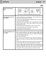
DIP
2 - INP
3 - LOOP
1 - AUTO
OFF position
ON position
ON
1
2
3
4
5
OFF
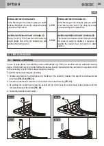
PIC. 22
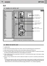
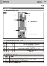
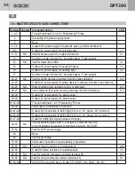
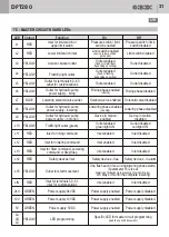
DPT280
UK


