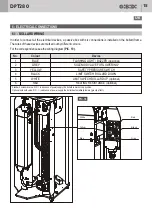


25
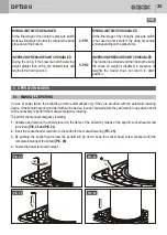
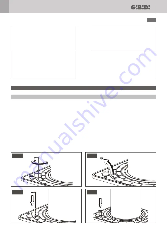
8.1 - MANUAL LOWERING
In case of power failure the bollards go down automatically only if they are provided with the automatic lowering
device. If the bollards are not provided with such a device, in case of power failure they will remain in up position and it
will be necessary to perform the manual emergency lowering.
To perform the manual emergency lowering:
1.
Unfasten and remove the dowel placed on the frame of the bollard by means of the specific socket head screw
(provided)
(PIC. 23 and PIC. 24
).
2.
Insert the socket head screw down to the button for the manual lowering
(PIC. 25)
.
3.
By pushing the socket head screw the bollard will go down; keep the socket head screw pressed until the
complete lowering of the bollard
(PIC. 26)
.
4.
Fasten the dowel removed in step 1.
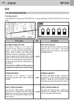
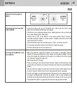
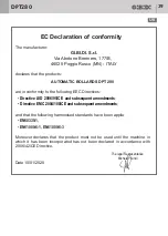
RISING LIMIT SWITCH ENABLED
At the final stage of the rising the pressure switch
works as limit switch in order to complete the rising
procedure of the bollard.
INVERSION PRESSURE SWITCH ENABLED
During the rising, if the pressure switch detects a
weight greater than 40 Kg, the bollard stops and
returns to the down position.
RISING LIMIT SWITCH DISABLED
At the final stage of the rising the pressure switch
is not used as limit switch; the rising procedure
ends depending on the preset time.
INVERSION PRESSURE SWITCH DISABLED
The function is excluded and then during the rising
the check on weight is disabled; in presence of
weights the device does not return to down
position.
4 - PR1
5 - PR2
8 - OPERATION MODES
PIC. 23
PIC. 24
PIC. 25
PIC. 26
DPT280
UK


