

33
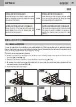
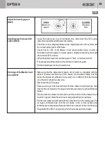
Manual lowering procedure
in case of power failure or
breakdown. (B004)
If the bollard is not equipped with a device for automatic lowering, in case of
power failure, each bollard can be manually lowered.
Proceed as follows:
• Some fitting screws are located in the bollard frame. Completely unscrew the
fitting screws in the frame and remove the frame cover. Use the Allen key
included in the scope of delivery.
• Remove the plastic cap (labelled: Replace me) from the frame.
• Guide the long side of the Allen key into the hole until it presses against the
button for manual lowering.
• Press and hold the Allen key until the bollard is fully lowered.
• Replace the plastic cap and the frame cover and retighten the fitting screws.
• Re-establish the 230 V supply.
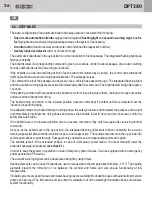
Repair/replacement of the 25
points flashing light integrated
in the head of the bollard
(optional item). (B003)
Adjustment/replacement of the
safety pressure switch. (B005)
• Every single led of the integrated multiled flashing light is composed by 3 light
points but only one point is used; in case of partial or total failure it is possible to
use the second or the third light point by following the procedure below.
• Turn the 230V power supply off – remove bollard's head – remove the black
cover placed under the head (where the power cable enters).
• There are 3 terminals on which are connected, on one side 3 black wires
(negative power supply of the 3 light points), on the other side only one black
wire is connected (this black wire powers the first point at -24VDC ).
• Move the black wire from the first terminal to the second or the third one to
power another light point.
• Test the proper operation of the multiled flashing light; if the test is positive
reassemble the head and complete the intervention; if the test is negative
replace the multiled flashing light.
• In case of replacement, request to GI.DI.DI S.r.l. the specific replacement
procedure for the flashing light and advise if the printed circuit of the flashing
light is orange (old version with IP 67 protection class) or white (current version
with IP 68 protection class).
ATTENTION – this check must be performed when the hydraulic pump is
“cold”
(not to be carried out after several consecutive movements which may
cause the oil heating in the hydraulic system).
The pressure switches are pre-set and hermetic to increase the IP protection
degree, in case of malfunction it is necessary to replace them.
• Bollard out of foundation box - bollard in down position - disconnect 230V
power supply.
• Unfasten the black oil filler cap of the oil-hydraulic unit by approximately two
turns (to reset the internal pressures of the hydraulic unit).
• Disconnect the pressure switch cable from the passive box on the bollard.
• Unfasten and remove the pressure switch with a spanner size 24, making sure
not to lose the gasket.
DPT280
UK
CONTINUES NEXT PAGE


