35
DPT280
UK
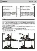
Adjust/replace the lower limit
switch. (B008)
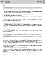
Exchange of the Master circuit
board. (B009
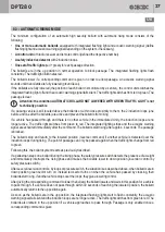
Adjust the lowering speed.
(B007)
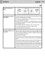
• Lower the bollard, put it out of foundation box, disconnect the 230V supply
(Disconnect possible additional accumulators).
• Check the correct allignment between the magnet placed on the cylinder and
the contact at the bottom of the frame.
• Check that L2 LED of the Master circuit (and possible Slave circuits) is
illuminated until the bollard is in down position. Slightly rotate the cylinder and
check that L2 LED is still on.
• When the bollard rises for more than approx. 15mm, L2 led must turn off.
• If necessary adjust the position of the limit switch and the support.
• Put the bollard back into the foundation box.
• Make sure that the replacement master circuit board is compatible with the
system. (Please note that even if the master circuit boards initially look the
same, the master circuit board of a Security Line is different from the master
circuit board of a High Security Line).
• Disconnect the 230 V supply.
• Remove all plug-in terminals with lines from the master circuit board (the lines
must not be unscrewed as the plug-in terminals can simply be pulled off the pin
bases).
• Take the defective master circuit board out of the control unit (the master circuit
board is in a green holder fixed onto a metal guide with quick couplings).
• Put the new master circuit board with the holder back onto the metal guide. Put
all plug-in terminals back onto the pin bases in the correct location (the
terminals are numbered and there are reference numbers on the circuit board).
• Re-establish the 230 V supply and perform the necessary function tests.

