

38
The bollard is in
high position and
a lowering com-
mand is given, the
bollard starts
lowering but it
stops in
intermediate
position. (C008)
The bollard is in
high position and
a lowering
command is
given, but the
bollard performs
the descent slowly
(only for products
equipped with
emergency
manual lowering).
(C010)
Even if it is
powered, the
bollard remains
for a long time in
high position, but
after a few days it
begins to lower
very slowly
(millimeter by
millimeter).
(C009)
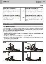
• The piston rod is very “dry” and
must be lubricated.
• The bollard was bumped
violently when in intermediate
position so the piston rod is
crooked.
• The lowering solenoid valve is
not powered.
• The solenoid valve or the
solenoid valve coil is broken.
When an hydraulic system remains
in operation for a long time, the in-
ternal pressure decreases gradual-
ly up to not being able to maintain
the moving cylinder in high position,
because of internal micro-leaks in
the system. The control unit ana-
lyzes the pressure level in the sys-
tem and when it is lower than a
certain value it performs an auto-
matic adjustment. When it occurs,
this problem may be caused by:
• The automatic pressure
a d j u s t m e n t h a s b e e n
accidentally excluded.
• The safety inductive detector
always in alarm (ON).
• Lubricate the piston rod.
• Replace the piston.
• Control (and if it is necessary replace) the solenoid
valve protection fuse in the master/slave units (master
unit PF4 - slave unit PF2).
• Replace the solenoid valve and/or the solenoid valve
coil.
• Verity that the dip switches 4 and 5 of the master board
are in OFF position.
• Reset the correct operation of the safety inductive
detector (sometimes the cause is the presence of a
metallic object on inductive loops).
DPT280
The bollard does
not work
or shows random
operations. (C011)
• The electrical guard switch of the
control unit is in OFF position.
• The protection fuses of the
master board are burned.
• The master board is broken and
it must be replaced.
• Reset the electrical guard switch in ON position and
check that it remains in this position.
• Check the 7 fuses of the master board and if it is neces-
sary replace the burned ones with some others with the
same values as reported on the printed circuit (ex. T1A).
• Replace the master board. Consult chapter 10:
SPECIFIC OPERATIONS.
UK


