

14
FUNZIONE
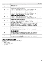
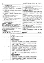
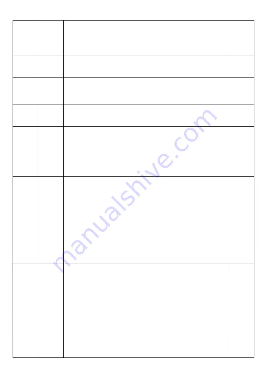
1.7
1.8
1.9
2.0
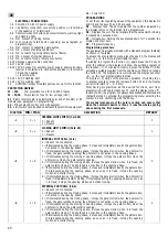
2.1
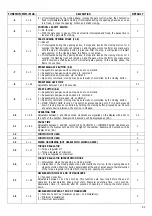
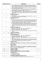
2.2
2.3
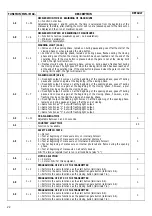
2.4
2.5
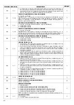
2.6
2.7
MIN
÷
MAX
0
÷
50
0
÷
6
0
÷
50
0
÷
6
0
÷
2
0
÷
7
0
÷
10
-
0
÷
5
0
÷
1
0
÷
2
DEFAULT
0
0
0
0
0
4
0
45
0
0
0
DESCRIZIONE
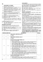
TEMPO DI RALLENTAMENTO A FINE MANOVRA
0
= Funzione non attiva.
Regolabile da 1 a 50 secondi. Questa funzione imposta quanto tempo, prima di fine lavoro,
deve iniziare la fase di rallentamento. Esempio: tempo lavoro= 40 secondi, tempo rallenta-
mento= 5 secondi, dopo 35 secondi di apertura o chiusura il motore rallenta.
VELOCITÀ DI RALLENTAMENTO A FINE MANOVRA
0
= Funzione non attiva (velocità massima - nessun rallentamento).
1
= Rallentamento minimo.
6
= Rallentamento massimo.
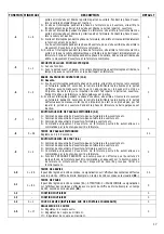
TEMPO DI RALLENTAMENTO AD INIZIO MANOVRA
0
= Funzione non attiva.
Regolabile da 1 a 50 secondi. Il tempo viene calcolato da inizio manovra, pertanto dopo la
partenza il motore avrà una velocità ridotta per il tempo impostato sul display, poi il motore
andrà alla velocità massima.
VELOCITÀ DI RALLENTAMENTO AD INIZIO MANOVRA
0
= Funzione non attiva (velocità massima - nessun rallentamento).
1
= Rallentamento minimo.
6
= Rallentamento massimo.
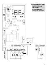
LAMPADA SPIA (21-18)
0
= Si accende in fase di apertura, rimane accesa in pausa e si spegne ad inizio fase di
chiusura o pigiando il pulsante di stop.
1
= Si accende in fase di apertura, rimane accesa in pausa, lampeggia in fase di chiusura e si
spegne solamente a finecorsa chiusura o a fine tempo lavoro. Pigiando il pulsante di
stop se il cancello non è a finecorsa chiusura, la lampada rimane accesa.
2
= Lampeggia lentamente in fase di apertura, si accende in pausa, lampeggia velocemente
in fase di chiusura. La lampada si spegne a finecorsa chiusura o a fine tempo lavoro.
Pigiando il pulsante di stop se il cancello non è a finecorsa chiusura, la lampada rimane
accesa.
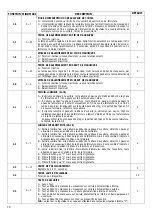
LAMPEGGIATORE (20-18)
0
= Uscita a luce fissa; si accende all’inizio della fase di apertura, si spegne in pausa e si
riaccende all’inizio della fase di chiusura.
1
= Uscita a luce fissa; si accende all’inizio della fase di apertura, si spegne in pausa e si
riaccende all’inizio della fase di chiusura, ma è possibile inserire un prelampeggio in fase
di chiusura.
2
= Uscita a luce fissa; si accende all’inizio della fase di apertura, si spegne in pausa e si
riaccende all’inizio della fase di chiusura, ma è possibile inserire un prelampeggio in fase
di chiusura e di apertura.
3
= Uscita a luce fissa; il lampeggiatore si accende ad inizio apertura, rimane acceso in pausa
e si spegne a fine chiusura.
4
= Stessa funzione di “0” ma con uscita lampeggiante.
5
= Stessa funzione di “1” ma con uscita lampeggiante.
6
= Stessa funzione di “2” ma con uscita lampeggiante.
7
= Stessa funzione di “3” ma con uscita lampeggiante.
TEMPO DI PRELAMPEGGIO
Regolabile da 0 a 10 secondi.
TEMPO LUCE DI CORTESIA
Funzione non disponibile.
TEST SICUREZZE
0
= Nessun test.
1
= Test ad inizio manovra solamente su fotocellula interna.
2
= Test ad inizio manovra solamente su fotocellula esterna.
3
= Test ad inizio manovra su fotocellula interna e fotocellula esterna.
4
= Test ad inizio manovra su fotocellula interna e costa in apertura.
5
= Test ad inizio manovra su tutti i dispositivi di sicurezza.
N.B.
: il test sul regolatore di coppia viene eseguito in tutte le situazioni (anche “0”).
SELEZIONE MOTORI
0
= 2 motori.
1
= 1 motore. N.B.: sulla presente apparecchiatura
PROGRAMMAZIONE TASTO 4 DEL TRASMETTITORE
0
= Esegue le stesse funzioni del pulsante di start (morsetti 8-6).
1
= Esegue le stesse funzioni del pulsante di passaggio pedonale (morsetti 9-6).
2
= Esegue le stesse funzioni del pulsante di chiusura (morsetti 7-6).


