
29
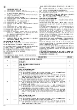
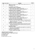
FUNÇÃO
.4
.5
.6
.7
.8
.9
1.0
1.1
1.2
1.3
1.4
1.5
MÍN
÷
MÁX
0
÷
6
0
÷
1
0
÷
2
0
÷
3
0
÷
99
0
÷
4
0
÷
98.
0
÷
80.
-
-
0
÷
1
0
÷
17
DEFAULT
0
0
0
0
20
0
30
0
0
0
0
0
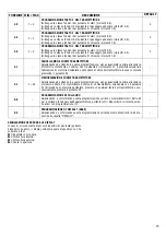
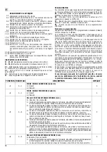
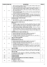
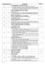
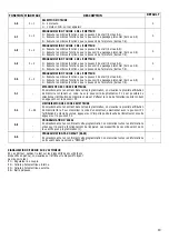
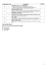
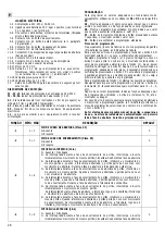
DESCRIÇÃO
2= Se interceptada durante a fase de encerramento do portão, interrompe o movimento do
mesmo portão e, quando a fotocélula é libertada, o portão parte de novo mas com
movimento de abertura. Durante a fase de abertura a fotocélula não está activa.
3= Se interceptada durante a fase de encerramento ou de abertura do portão, interrompe o
movimento do mesmo portão. Quando a fotocélula é libertada, o portão parte de novo
com movimento de abertura.
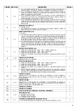
4= Se interceptada durante a fase de encerramento do portão, interrompe o movimento do
mesmo portão e, quando a fotocélula é libertada, o portão parte de novo com movimen-
to de encerramento. Durante a fase de abertura a fotocélula não está activa.
5= Se interceptada durante a fase de encerramento do portão, interrompe e inverte
imediatamente o movimento do mesmo portão.
Se interceptada durante a fase de abertura, a fotocélula, logo que é libertada, interrompe
o movimento de abertura e dá início ao encerramento.
6= Se interceptada durante a fase de encerramento do portão, interrompe o movimento do
mesmo portão. Quando a fotocélula é libertada, o portão parte de novo com movimento
de encerramento. Se interceptada durante a fase de abertura, a fotocélula, logo que é
libertada, interrompe o movimento de abertura e dá início ao encerramento.
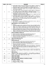
SEGURANÇA DAS FOTOCÉLULAS
0= Nenhuma função
1= Se a fotocélula for interceptada e libertada com o portão aberto em pausa, o tempo de
pausa anula-se e o portão parte para o encerramento.
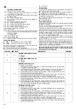
BANDA SENSÍVEL EM FASE DE ABERTURA (11-6)
0= Ausente
1= Se interceptada durante a fase de abertura, interrompe e inverte o movimento durante 2
segundos, a lâmpada pisca-pisca ficará acesa e o portão não efectuará qualquer manobra
enquanto não se carregar no botão de stop ou de emergência; depois de dado o stop
verificar-se-á um impulso de start que fará partir de novo o portão com movimento de
abertura. A banda sensível não está activa durante a fase de encerramento do portão.
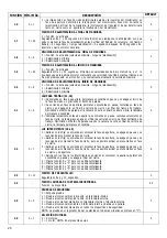
2= Se interceptada durante a fase de abertura, interrompe e inverte o movimento durante 2
segundos, a lâmpada pisca-pisca ficará acesa e o portão não efectuará qualquer manobra
enquanto não lhe chegar um impulso de start que o fará partir de novo com movimento
de abertura. A banda sensível não está activa durante a fase de encerramento do portão.
BOTÃO DA PASSAGEM DE PEÕES (9-6)
0= Comando sequencial de abertura-pausa-encerramento-stop-abertura, etc..
1= Comando sequencial de abertura-pausa-encerramento-abertura, etc..
2= Comando sequencial de abertura-encerramento-abertura, etc..
3= Comando exclusivamente de abertura; o encerramento poderá ser automático ou
comandado pelo botão de encerramento.
TEMPO DE PASSAGEM DOS PEÕES
Regulável de 0 a 99 segundos
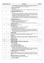
BOTÃO DE START (8-6)
0= Comando sequencial de abertura-pausa-encerramento-stop-abertura, etc..
1= Comando sequencial de abertura-pausa-encerramento-abertura, etc..
2= Comando sequencial de abertura-encerramento-abertura, etc..
3= Comando exclusivamente de abertura; o encerramento poderá ser automático ou
comandado pelo botão de encerramento.
4= Função HOMEM-MORTO. O botão só activa a abertura se for pressionado; o encerramento
poderá ser comandado mantendo o botão de encerramento pressionado. A intervenção
de qualquer dispositivo de segurança determina a interrupção do movimento.
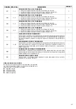
TEMPO DE TRABALHO
Regulável de 0 a 198 segundos. A indicação das centenas no mostrador é dada pela presença
de um ponto a seguir ao algarismo da direita. Exemplo: um tempo de 198 segundos será
exibido (98.).
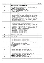
TEMPO DE PAUSA
Regulável de 0 a 180 segundos (80.). ATENÇÃO: 0 = PAUSA INFINITA. A indicação das
centenas no mostrador é dada pela presença de um ponto a seguir ao algarismo da direita.
Exemplo: um tempo de 180 segundos será exibido (80.).
FUNÇÃO NÃO UTILIZADA
FUNÇÃO NÃO UTILIZADA
GOLPE DE ARÍETE (NÃO UTILIZÁVEL EM PORTÕES DE CORRER)
REGULADOR DE BINÁRIO
0= Exclusão do regulador de binário.
1= Regulador de binário no mínimo.
17= Regulador de binário no máximo


