Subject to alterations, 03.06.20
11/32
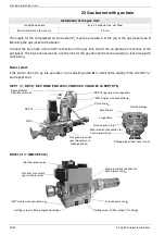
Set the electrodes
16 Set the electrodes
The electrodes are preset at the factory.
17 Flame monitor with
ionisation control
If an AC current is applied between the burner and
the ionisation rod, a DC current flows due to the rec-
tifying effect of the flame. This ionisation current
forms the flame signal and is amplified and passed
to control box. A flame cannot be faked because the
rectifying effect no longer works if there is a short-
circuit between the sensor electrode and the burner.
Measuring the ionisation current
The ionisation current must be measured during
burner start-up and maintenance or after a fault in-
dication in the control box. This done by disconnect-
ing the plug in the ionisation cable and connecting it
to the ionisation measuring cable.
The measurement must be carried out directly after
post-ignition during the safety time!
The ionisation current must be at least
1.5 µA. Values below 1.5 µA will result in unreliable
operation or a direct fault shut-down. In this case,
the ionisation rod and the baffle plate must be
cleaned. Bend ionisation rod if necessary. If the ion-
isation rod is defective, replace it. Possibly reverse
the polarity of the ignition transformer on the primary
side. Check the cable for moisture and dry it if nec-
essary.
Ignition electrode
Ionisation
electrodes


