background image

Subject to alterations, 03.06.20

19/32

Start-up and calibration
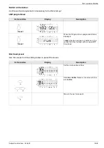
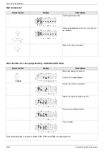
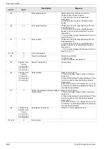
LMV phase display

Display

Description

Ph00

Fault phase

Ph01

Safety phase

Ph10

Go home

Ph12

Standby (stationary)

Ph22

Blower start-up time (blower motor = ON, safety valve = ON)

Ph24

Run in pre-air position

Ph30

Pre-air time

Ph36

Run in ignition position

Ph38

Pre-ignition phase

Ph39

Leakage check filling time (test pressure switch min for installation between fuel valve 1 and 
fuel valve 2)

Ph40

First safety time (ignition transformer ON)

Ph42

First safety time (ignition transformer OFF)

Ph44

Interval 1

Ph50

Second safety time

Ph52

Interval 2

Ph60

Operation 1 (stationary)

Ph62

Maximum time small-load setting (operation 2, preparation decommissioning, run in small-load 
setting)

Ph70

After-burn time

Ph72

Run in post-ventilation position

PH74

Post-ventilation time (no external leak test)

Ph78

Post-ventilation time (abort when power controller ON)

Ph80

Leakage check idle time

Ph81

Leakage check test time atmospheric pressure, atmosphere test

Ph82

Leakage check filling test, filling

Ph83

Leakage check test time gas pressure, pressure test

Ph90

Gas shortage waiting time

Summary of Contents for MG20-ZM-L-LN Series

Page 1: ...Issued in June 2020 Subject to tech modifications to improve the product Gas Technical Information Installation Instructions MG20 ZM L LN GB...

Page 2: ...nts 7 12 Electrical connection 8 13 Air flap positioning motor 9 14 Air pressure switch 9 15 Gas pressure monitor 10 16 Adjusting the ignition electrode 11 17 Measuring the ionisations current 11 18 A...

Page 3: ...s Before installing the gas burner please check the scope of delivery Scope of delivery burner housing gas jacket with burner pipe mount ing kit documentation and gas train Gas installation and commis...

Page 4: ...enuine parts or where the equipment has been used for purposes for which it was not intend ed 4 Operating instructions The operating instructions together with this techni cal information leaflet must...

Page 5: ...size Allen key The air pressure switch for the gas train must be at the top Burner type Technical specifications MG20 1 ZM L LN MG20 2 ZM L LN Burner output in kW 224 860 247 1350 Gas type Natural ga...

Page 6: ...on the burner housing in the gas jacket hinge and secure it with a rod The burner is now in the service position Attach the ignition and ionisation cable to the igni tion and ionisation electrodes Car...

Page 7: ...HLWH 0 0 09 0 HDUE 8UVSU 63B VWURNRVFK DWXP DWXP UVHW W GXUFK RLOHU bQGHUXQJ HSU UVDW YRQ QHUWHFK PE UHQQHU XQG HL V VWHPH D 1DPH HLFKQ 1U GHQW 1U HVVHO XQGH QVFKOXVV HVVHO ZHLVWXILJ QVFKOXVV HVVHO PR...

Page 8: ...r must be of the flexi ble type To access the firing unit the cover must be brought to the service position To do this remove the secur ing screws 1 and fold the cover down to the left After wiring ha...

Page 9: ...rners The motor is activated electron ically via the microprocessor controlled control box Do not open the air flap actuator while it is under voltage The internal optics would be destroyed No warrant...

Page 10: ...DK the GDW MIN jumper has to be replaced with the connection of the gas pressure switch MIN When using the gas cycle MB VEF 412 the connec tion is made via the 7 pin connector and is only evaluated as...

Page 11: ...tion current must be measured during burner start up and maintenance or after a fault in dication in the control box This done by disconnect ing the plug in the ionisation cable and connecting it to t...

Page 12: ...XV UXQQLQJ 6DIHW YDOYH 69 JQLWLRQ XHO YDOYH 9 3LORW YDOYH 39 3UHVVXUH VZLWFK PLQ JDV PLQ RLO 3 PLQ RQQHFWLRQ 20 XLOGLQJ DXWRPDWLRQ FWXDWRU IXHO FWXDWRU DLU 96 UHTXHQF FRQYHUWHUV 1 3 6DIHW FKDLQ 3RZHU...

Page 13: ...in parametrisation mode Unlock in case of fault One menu level down Button Reduce value For navigating in curve setting information and service mode Button Increase value For navigating in curve setti...

Page 14: ...th voltage gas pressure is built up and there is no demand for heat The firing managers are parametrized in the factory OFF UPr appears in the display during first start up Enter password Action butto...

Page 15: ...the setting tables to preset the values Action button Display Description When the firing machine is programmed run is displayed i reset skips the next steps an continues at the section Start heat set...

Page 16: ...oad air flap Hold down button A and set the value with the or button Move to the next curve point Action button Display Description When heat demand is present Confirm with i reset button Burner start...

Page 17: ...button to confirm Ignition ON Valves ON Ignition OFF Flame in start position When transferring P1 to P2 for the first time CALC appears briefly The curve points P2 to P9 are calculated auto matically...

Page 18: ...Action button Display Description Check the high load setting via the gas flow at the gas meter or compare the nozzle pressure with the values stated in 24 Adjustment tables Hold down A button and use...

Page 19: ...fety time ignition transformer ON Ph42 First safety time ignition transformer OFF Ph44 Interval 1 Ph50 Second safety time Ph52 Interval 2 Ph60 Operation 1 stationary Ph62 Maximum time small load setti...

Page 20: ...tion and repeat start KEV 1 KEV2 KEV DN65 VGD20 40 VGD20 50 VGD40 65 all SKP15 75 KEV412 1 MB VEF 412 Installation of the gas train Installation position only in horizontal line not tilted Minimum dis...

Page 21: ...too low O2 too high Change in direction if CO2 too high O2 too low Small flame N setting Exhaust gas analysis values Change in direction if CO2 too low O2 too high Change in direction if CO2 too high...

Page 22: ...ospheric pressure B acc to Tab 989 mbar Gas pressure PG at gas meter 20 mbar Gas temperature G 16 C Boiler output Qn 220 kW Efficiency K assumed 92 Calorific value Hi n 10 4 kWh m3 Gas flow in standar...

Page 23: ...Stage 1 Stage2 Stage1 Stage2 Stage1 Stage2 Stage1 Stage2 Stage1 Stage2 Stage1 Stage2 Stage1 Stage2 Stage1 450 224 419 26 0 9 22 7 3 2 1 49 9 24 8 5 7 1 6 44 6 22 2 7 4 2 0 17 4 8 7 520 260 484 33 0 12...

Page 24: ...5 66 5 33 3 5 4 2 0 59 5 29 7 7 5 2 4 23 2 11 6 800 400 736 40 20 22 12 8 4 2 88 7 44 3 10 0 3 3 79 3 39 7 12 8 3 7 30 9 15 4 1000 500 920 90 25 22 19 6 5 2 110 9 55 4 15 3 4 1 99 1 49 6 19 5 5 4 38 6...

Page 25: ...ide is leaking Check whether the pressure switch for the leak test is closed when gas pressure is applied Check wiring for short circuit 14 0 POC open Check whether valve NC contact is closed 1 POC cl...

Page 26: ...ble defective 95 3 Ignition trans former 4 Fuel valve 1 5 Fuel valve 2 6 Fuel valve 3 External supply NOC Check wiring 96 3 Ignition trans former 4 Fuel valve 1 5 Fuel valve 2 6 Fuel valve 3 Relay wel...

Page 27: ...just ments log Boiler type Gas fitting Measured values min max Date P0 start point P1 min load P9 max load Flue gas temperature C Carbon dioxide CO2 level O2 content CO level Flue mbar Nozzle pressure...

Page 28: ...28 32 03 06 20 Subject to alterations Exploded view drawing spare parts list 27 Exploded view drawing spare parts list ZBZ_2 529...

Page 29: ...Sight glass cover 5 47 50 12106 11 Hood MG20 1 47 90 24857 12 Inspection glass with seal 5 36 50 11544 13 Fan wheel 218 x 80 for MG20 1 1 36 90 11540 01 13 Fan wheel 224 x 82 for MG20 2 1 47 90 24847...

Page 30: ...s We Enertech GmbH Adjutantenkamp 18 in D 58675 Hemer declare under our responsibility that gas burner type MG20 is conform with the regulations of these directives MD2006 42 EG EMC2014 30 EU GAD 2016...

Page 31: ...Subject to alterations 03 06 20 31 32 Declaration of Conformity for Gas Burners...

Page 32: ...be duplicated without our written permission given in advance Subject to alterations 29 Dimensions all dimensions are given in mm 30 Working ranges Working ranges acc to DIN EN 676 The working ranges...

Reviews: