


2/32
03.06.20, Subject to alterations
Contents
1
General information ................................................................................................................... 3
2
Checking the scope of delivery and electrical ratings ................................................................ 3
3
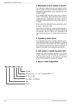
Maintenance and customer service ........................................................................................... 4
4
Operating instructions ................................................................................................................ 4
5
Instruction of operating personnel.............................................................................................. 4
6
Key for code designation ........................................................................................................... 4
7
Technical specifications .............................................................................................................. 5
8
Boiler connection dimensions .................................................................................................... 5
9
Mounting the gas jacket mantel at the boiler .............................................................................. 5
10
Mounting the burner housing on the gas jacket (service position) ............................................. 6
11
Terminal diagram connector pin assignments ............................................................................ 7
12
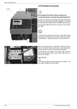
Electrical connection ................................................................................................................... 8
13
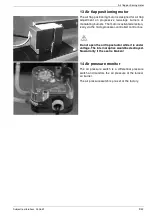
Air flap positioning motor .......................................................................................................... 9
14
Air pressure switch ..................................................................................................................... 9
15
Gas pressure monitor ............................................................................................................... 10
16
Adjusting the ignition electrode ................................................................................................. 11
17
Measuring the ionisations current ............................................................................................. 11
18
Adjusting the mixer head ......................................................................................................... 12
19
Connection diagram LMV27 ..................................................................................................... 12
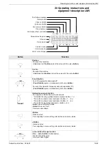
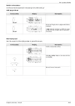
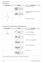
20
Operating instructions and equipment description LMV............................................................ 13
21
Start-up and calibration ............................................................................................................ 14
22
Gas burner with gas train KEV
II
1 ½", KEV 2", KEV412 1 1/2“, KEV300 1“, KEV DN65 ........... 20
23
Calculation principles for gas burner adjustment .................................................................... 22
24
Adjustment tables .................................................................................................................... 23
25
Error code list LMV .................................................................................................................. 25
26
Adjustments log ........................................................................................................................ 27
27
Exploded view / spare parts list................................................................................................. 28
28
Declaration of Conformity for Gas Burners ............................................................................... 30
29
Overall dimensions .................................................................................................................. 32
30
Working ranges ........................................................................................................................ 32


