


22/32
03.06.20, Subject to alterations
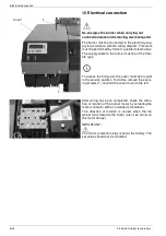
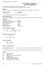
Calculation principles for gas burner adjustment
23 Calculation principles for
gas burner adjustment
The values given in the tables are setting values for start-up.
The necessary system adjustment must be newly determined in each case.
General:
The calorific value (H
i,n
) of fuel gases is generally specified for the normal state (0°C, 1013 mbar).
Natural gas type E
H
i,n
= 10.4 kWh/m
3
Natural gas type LL
H
i,n
= 9.3 kWh/m
3
Gas counters measure the volume of gas in the operational state.
Gas flow determination:
To allow the heat generator load to be adjusted correctly, the gas flow rate must be determined in advance.
Example:
Height above sea level
230 m
Atmospheric pressure B (acc. to Tab.) 989 mbar
Gas pressure P
G
at gas meter
20 mbar
Gas temperature
ϑ
G
16°C
Boiler output Q
n
220 kW
Efficiency
η
K
(assumed)
92%
Calorific value H
i,n
10.4 kWh/m
3
Gas flow in standard state (V
n
)
Gas flow in operating state (V
B
)
Conversion factor (f)
Annual average air pressure
Legend:
Q
n
=
boiler output [kW]
η
K
=
efficiency [%]
H
i,n
=
lower standard calorific value [kWh/m
3
]
f =
conversion factor
B =
atmospheric pressure [mbar]
p
G
=
gas pressure at gas meter [mbar]
ϑ
G
=
gas temperature at gas meter [°C]
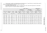
Average geodetic altitude of the
supply region above sea level [m]
from
1
51
101
151
201
251
301
351
401
451
501
551
601
651
701
to
0
50
100
150
200
250
300
350
400
450
500
550
600
650
700
750
Annual average of air pressure
(mbar) 1016 1013 1007 1001 995
989
983
977
971
965
959
953
947
942
936
930
V
n
Q
n
η
k
H
×
i n
,
--------------------
220
kW
0 92
10
×
4
kWh
m
3
-----------
,
,
----------------------------------------
=
23
m
3
h
------
=
=
V
B
V
n
f
------
23
m
3
h
------
0 94
,
-------------
=
24
m
3
h
------
=
=
f
B P
G
+
1013
--------------
273
273
ϑ
G
+
--------------------
×
=


