Su
b
je
c
t t
o
a
lte
ra
tio
n
s,
0
3
.0
6
.2
0
2
3
/3
2
Ad
ju
s
tm
e
n
t t
a
b
le
s
2
4
A
d
ju
s
tm
e
n
t t
a
b
le
s
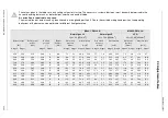
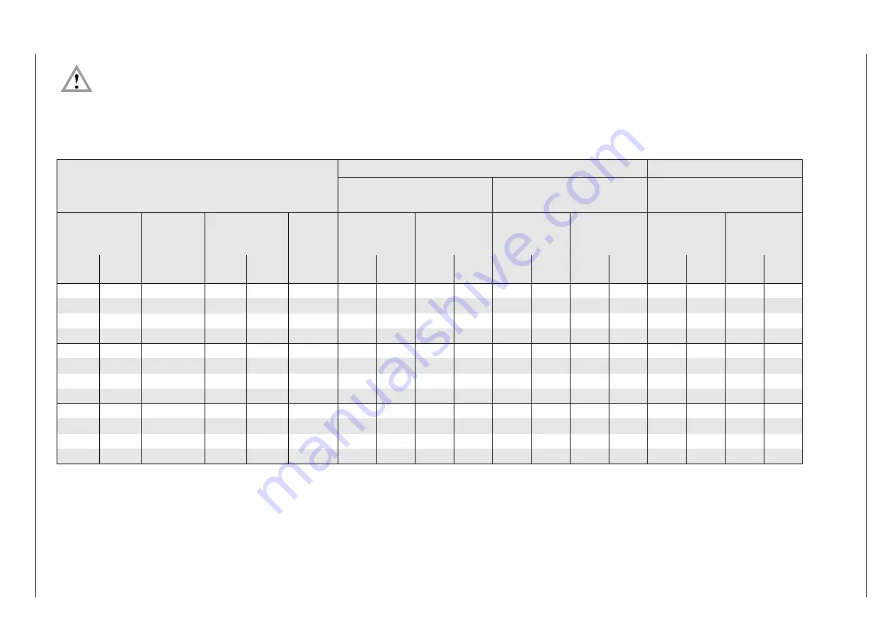
The values given in the tables are only setting values for start-up. The necessary system adjustment must be newly determined in the
case of deviating data such as boiler output, calorific value and altitude.
A correction is required in any case.
The maximal burner output can only be achieved in mixing head position 0. Due to the variable mixing head position, the operating
behaviour of the burner can be optimised for different heat generators.
MG20/1-ZM-L-LN
MG20/2-ZM-L-LN
Natural gas LL
Hi,n = 9.3
[
kWh/m
3
]
Natural gas E
H
i,n
= 10.4 [kWh/m
3
]
LPG
H
i,n
= 25.89 [kWh/m
3
]
Burner output
[kW]
Boiler output
η
= 92%
[kW]
Air flap
position
[ ° ]
Burner
heat pos.
[mm]
Gas nozzle
pressure
[mbar]
Gas flow rate
[m
3
/h]
Gas nozzle
pressure
[mbar]
Gas flow rate
[m
3
/h]
Gas nozzle
pressure
[mbar]
Gas flow rate
[m
3
/h]
Stage 2
Stage 1
Stage2
Stage1
Stage2 Stage1 Stage2 Stage1 Stage2 Stage1 Stage2 Stage1 Stage2 Stage1 Stage2 Stage1
450
224
419
26.0
9
22
7.3
2.1
49.9
24.8
5.7
1.6
44.6
22.2
7.4
2.0
17.4
8.7
520
260
484
33.0
12
22
9.6
2.7
57.6
28.8
7.5
2.1
51.5
25.8
9.5
2.7
20.1
10.0
600
300
558
40.0
14
22
12.0
3.5
66.5
33.3
9.4
2.7
59.5
29.7
12.1
3.6
23.2
11.6
740
370
688
90.0
19
22
14.7
5.0
82.0
41.0
11.5
3.9
73.4
36.7
17.4
5.2
28.6
14.3
560
280
521
30.5
13
10
7.9
2.7
62.1
31.0
6.2
2.1
55.5
27.8
9.4
2.9
21.6
10.8
640
320
595
36.0
17
10
10.3
3.5
70.9
35.5
8.1
2.7
63.4
31.7
11.8
3.6
24.7
12.4
760
380
707
51.0
21
10
14.5
4.8
84.2
42.1
11.3
3.8
75.3
37.7
16.0
4.8
29.4
14.7
813
410
756
90.0
22.5
10
16.2
5.2
90.1
45.4
12.7
4.1
80.6
40.6
18.0
5.5
31.4
15.8
600
300
558
30.0
10
0
9.1
2.8
66.5
33.3
7.1
2.2
59.5
29.7
9.0
2.9
23.2
11.6
680
340
632
34.0
13
0
11.2
3.5
75.4
37.7
8.8
2.7
67.4
33.7
11.3
3.5
26.3
13.1
780
390
725
44.0
17
0
14.3
4.3
86.5
43.2
11.2
3.4
77.3
38.7
14.5
4.3
30.1
15.1
860
430
800
90.0
20
0
17.4
5.0
95.3
47.7
13.6
3.9
85.2
42.6
17.4
5.1
33.2
16.6

